
Light mixer and backlight module having the same

Active Publication Date: 2008-06-12
HKC CORP LTD
View PDF13 Cites 59 Cited by
  • Summary
  • Abstract
  • Description
  • Claims
  • Application Information

AI Technical Summary

Benefits of technology

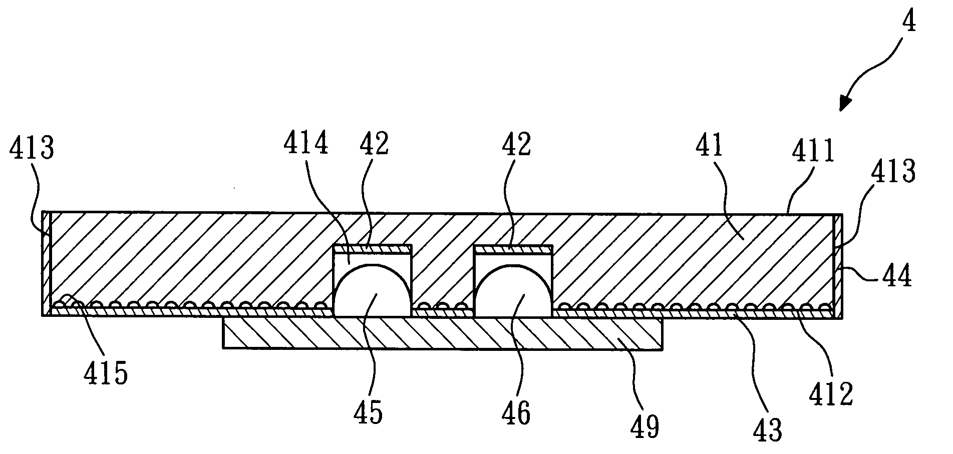
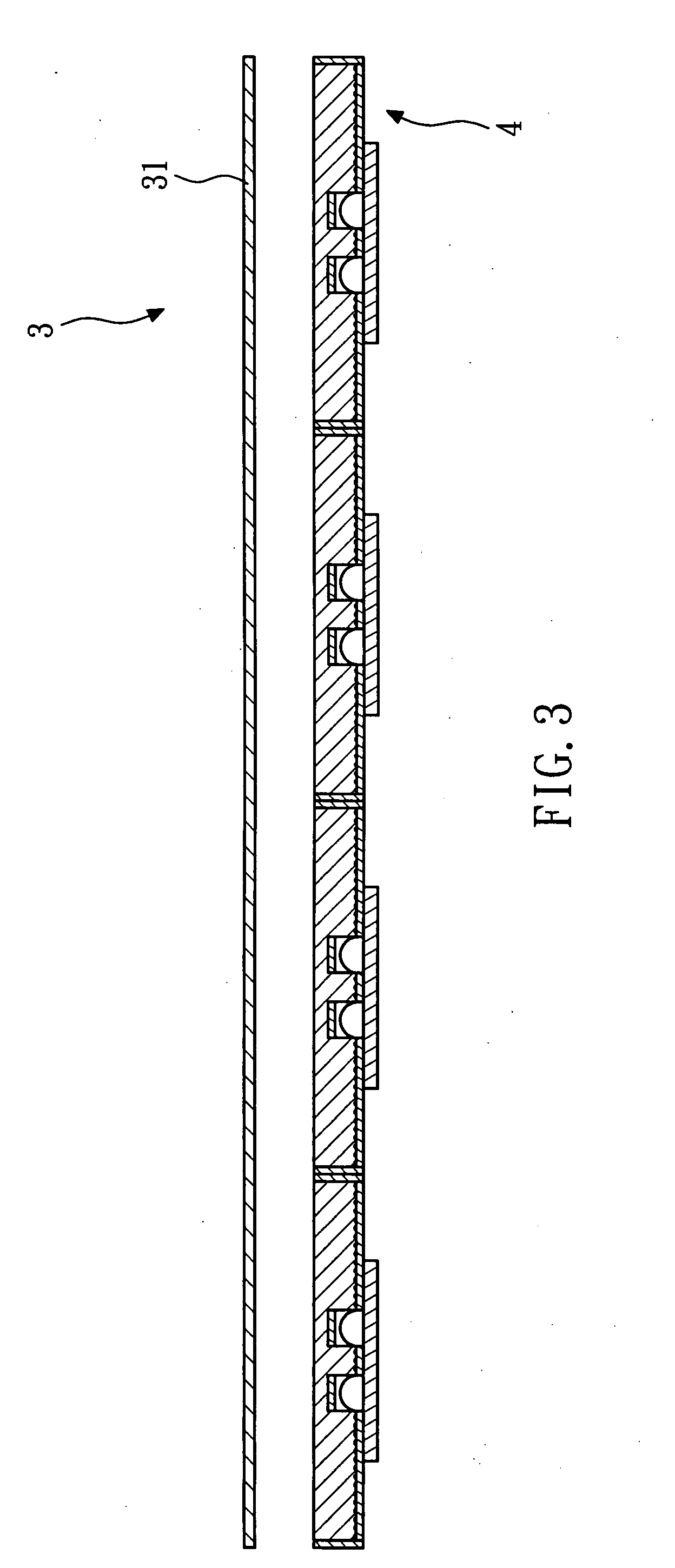
[0009]The backlight module is formed by the modularized light mixers, without requiring a large light guide plate used in the prior art, and thus can be conveniently fabricated; the fabricating process is relatively simple, the fabricating cost is relatively low, and it is simple and convenient to maintain. Furthermore, the special design of the light mixers may improve the light mixing efficiency and the luminance, so that the area of the light mixing plate reaches 50 mm*50 mm, and even up to 120 mm*120 mm, and thus the amount of the light mixers in the backlight module can be reduced, and accordingly, the amount of the light sources is reduced.

Problems solved by technology

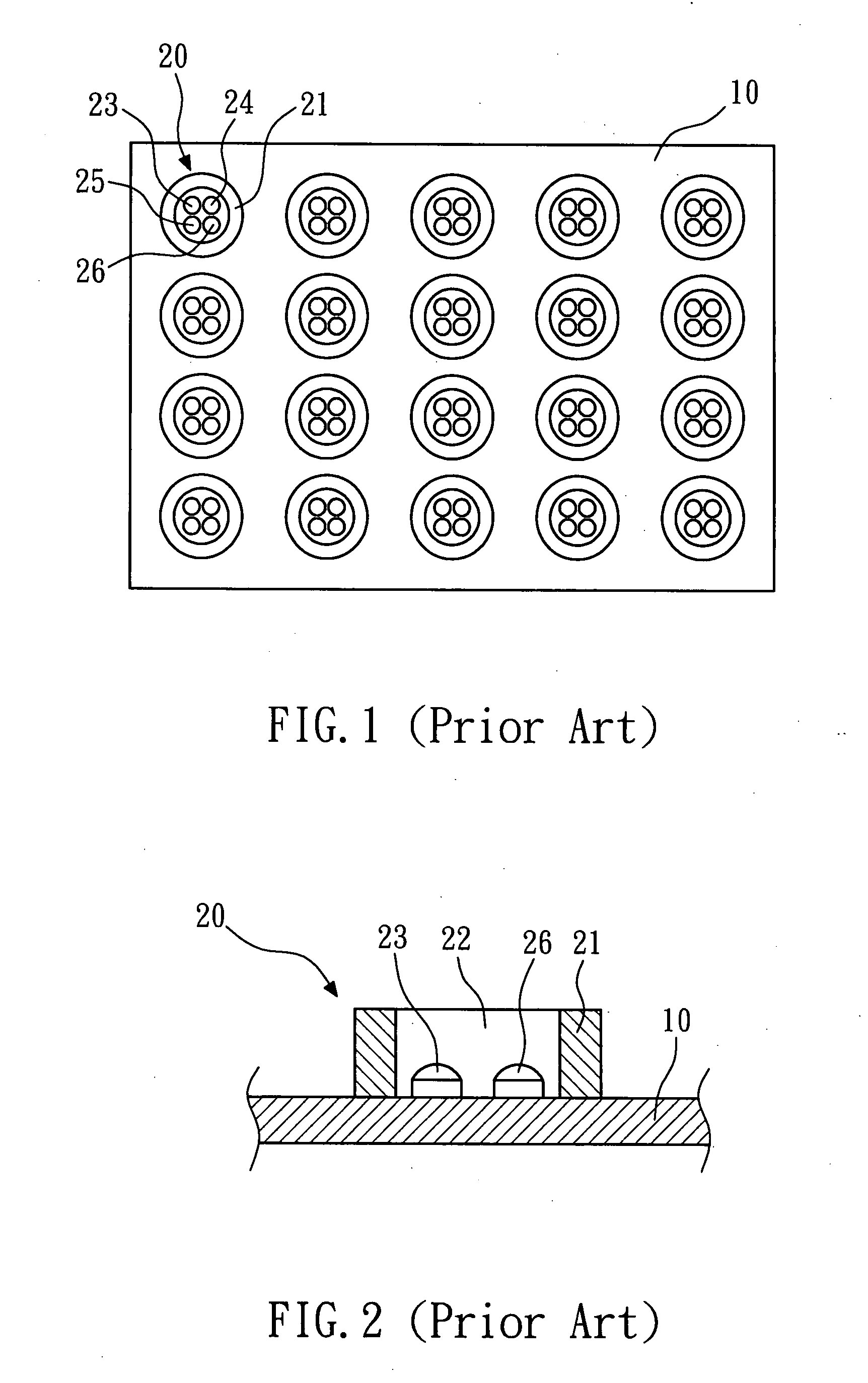
However, since the LEDs 23, 24, 25, and 26 naturally mix the light in the air, the light mixing efficiency is not high, so the overall thickness of the conventional backlight module cannot be effectively reduced.
In addition, the amount of LEDs required by the conventional backlight module cannot be effectively reduced, which not only consumes a lot of power, but also raises the fabricating cost.

Method used


Image

  • Light mixer and backlight module having the same
  • Light mixer and backlight module having the same
  • Light mixer and backlight module having the same

Examples


example 1

[0033]Twenty-eight light mixers 7 (FIG. 8) of the fourth embodiment of the present invention are arranged into a 4*7 array, and the process for arranging LEDs in each light mixer 7 is described as follows. LED 45 is the red LED, LED 46 is the green LED, LED 47 is the green LED, and LED 48 is the blue LED. Next, a color brilliance meter is used for measurement at 50 cm from the light mixers 50, and the measuring results are listed as follows. (1) When the reflectance of the semi-permeable layer 44 is 100%, the luminance is 4200 nit, the luminance uniformity is 77.2%, and the color uniformity is 0.022. (2) When the reflectance of the semi-permeable layer 44 is 50%, the luminance is. 4277.56 nit, the luminance uniformity is 82.35%, and the color uniformity is 0.023. (3) When the reflectance of the semi-permeable layer 44 is 0%, the luminance is 4342.84 nit, the luminance uniformity is 88.37%, and the color uniformity is 0.031.

example 2

[0034]Twenty-eight light mixers 7 (FIG. 8) of the fourth embodiment of the present invention are arranged into a 4*7 array, and the process for arranging LEDs in each light mixer 7 is described as follows. LED 45 is the blue LED, LED 46 is the green LED, LED 47 is the green LED, and LED 48 is the red LED. The reflectance of the semi-permeable layer 44 of each light mixer 7 is 0%. Next, a color brilliance meter is used for measurement at 50 cm from the light mixers 50, and the measuring results are listed as follows: the luminance is 4332.74 nit, the luminance uniformity is 86.78%, and the color uniformity is 0.011.


PUM


Abstract

A light mixer and a backlight module having the light mixer are provided. The backlight module includes a plurality of light mixers and a diffuser. The light mixers are arranged on a plane in an array. Each light mixer includes a light mixing plate, a plurality of light sources, a plurality of upper reflecting layers, a lower reflecting layer, and a semi-permeable layer. The light mixing plate has an upper surface, a lower surface, a peripheral surface, and a plurality of receiving holes. The light sources are respectively located in the receiving holes. The upper reflecting layers are respectively located right above the light sources. The lower reflecting layer is located on the lower surface of the light mixing plate. The semi-permeable layer wraps the peripheral surface of the light mixing plate. The diffuser is located above the light mixers. Therefore, the fabricating process of the backlight module is relatively simple, the fabricating cost is relatively low, and it is simple and convenient to maintain. Furthermore, the special design of the light mixers enhances the light mixing efficiency and the luminance.

Description

BACKGROUND OF THE INVENTION[0001]1. Field of the Invention[0002]The present invention relates to a light mixer and a backlight module having the light mixer. More particularly, the present invention relates to a modularized light mixer and a backlight module having the light mixer.[0003]2. Description of the Related Art[0004]FIG. 1 is a schematic top view of a conventional backlight module disclosed in US Patent No. US 2005 / 0259195A1 with a diffuser omitted. FIG. 2 is a schematic cross-sectional view of FIG. 1. The conventional backlight module includes a diffuser (not shown), a reflector 10, and a plurality of light guide blocks 20.[0005]The light guide blocks 20 are arranged in an array and fixed on the reflector 10, and the light guide blocks 20 are spaced apart from each other by an appropriate distance. Each light guide block 20 includes a light guide body 21, a receiving space 22, and four LEDs 23, 24, 25, and 26. The light guide body 21 is made of an acrylate resin for the li...

Claims


Application Information

Patent Timeline
IPC IPC(8): F21V7/00
CPCG02B5/0247G02B6/0021G02B6/0078G02B6/0046G02B6/0055G02B6/0036
Inventor TSAI, SHEN-YINKUO, CHIN-LUNGKUO, YAO-YUANLEE, I-CHANG
Owner HKC CORP LTD
Learn More