Coloring electroanatomical maps to indicate ultrasound data acquisition

a technology of electroanatomy and ultrasound, applied in the field of mapping and reconstruction of body organs, can solve the problems of difficult for users to determine when adequate image data have been acquired, and block the user's view of the heart chamber by other tissue reflection,

Active Publication Date: 2008-06-12
BIOSENSE WEBSTER INC
View PDF17 Cites 89 Cited by
  • Summary
  • Abstract
  • Description
  • Claims
  • Application Information

AI Technical Summary

Benefits of technology

[0008]According to disclosed embodiments of the invention, a three-dimensional representation of the structure, such as a functional map, e.g., an electroanatomical map, is displayed and marked, typically by application of pseudocolor, during acquisition of ultrasound data in order to show the progress of data acquisition. For example, the planes of intersection of successive ultrasound two-dimensional fans that are acquired may be marked on an electroanatomical map as lines or colored regions on the map surface. This display enables the operator to determine regions where sufficient ultrasound data have been captured, and guides the operator to areas of the heart chamber where additional data collection is still needed. Various color schemes are used to indicate the relative sufficiency of data collection.

Problems solved by technology

However, this blocks the user's view of the heart chamber by other tissue reflection, e.g., from other chambers or organs.
Therefore, it is difficult for the user to determine when adequate image data have been acquired or whether details are still missing.

Method used


Image

  • Coloring electroanatomical maps to indicate ultrasound data acquisition
  • Coloring electroanatomical maps to indicate ultrasound data acquisition
  • Coloring electroanatomical maps to indicate ultrasound data acquisition

Examples


embodiment 1

Alternate Embodiment 1

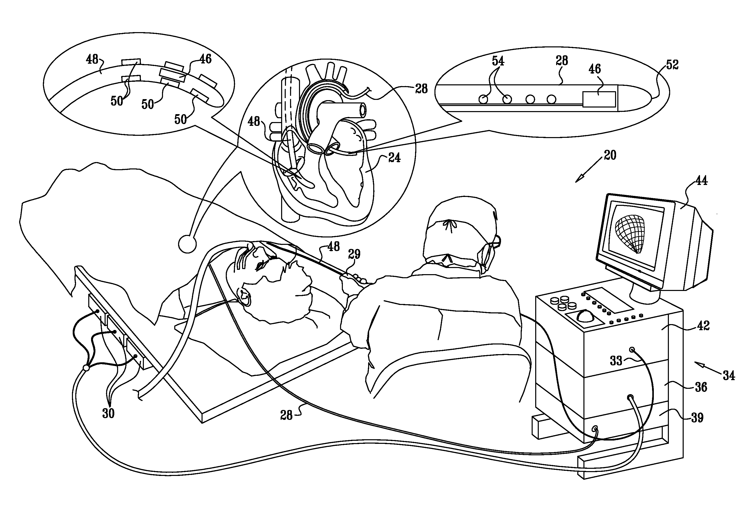
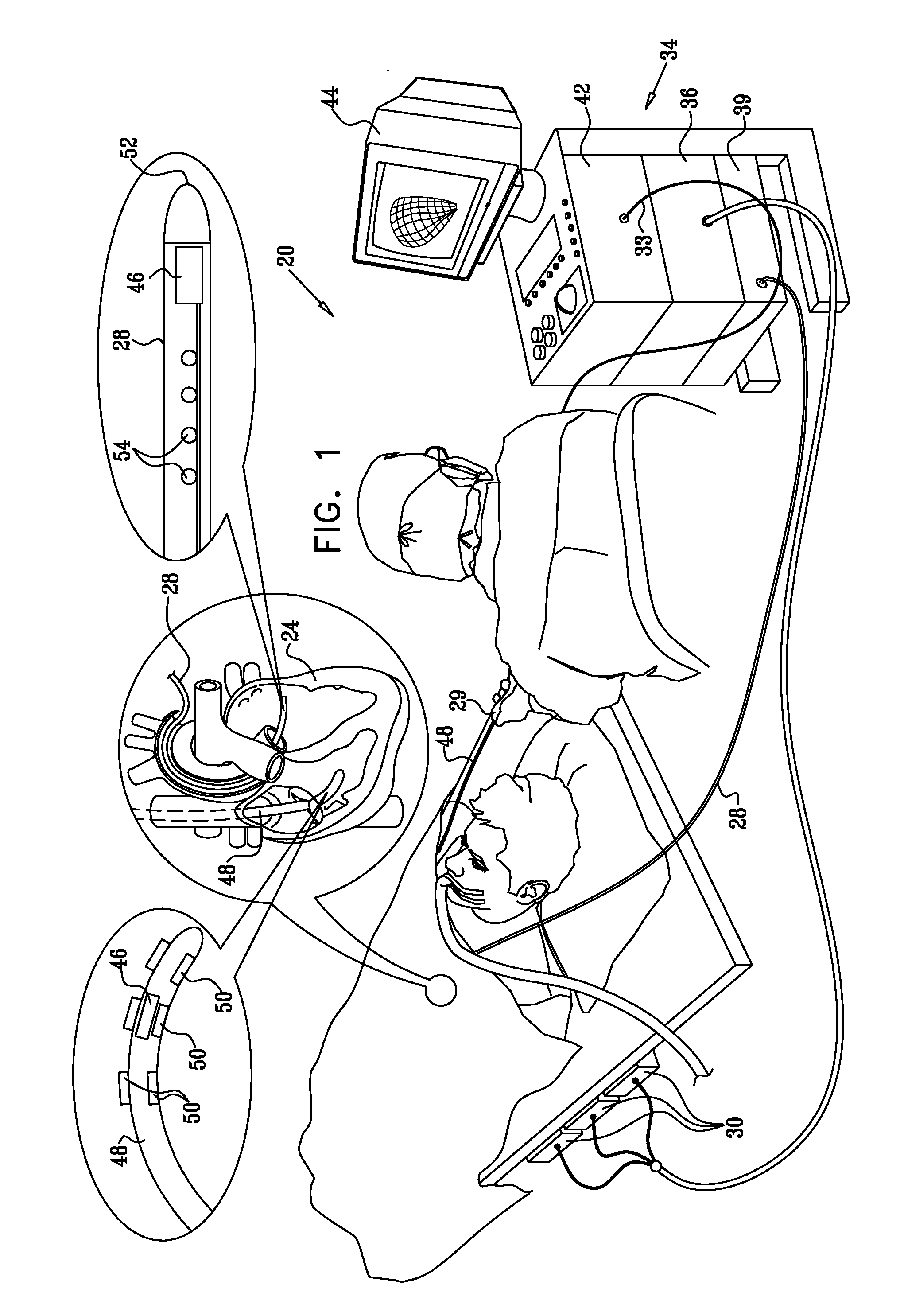
[0058]Reference is now made toFIG. 4, which is a detailed flow chart of a method of coloring an electroanatomical map or other functional map to indicate ultrasound data acquisition in accordance with an alternate embodiment of the invention. It will be understood that “coloring”, also referred to herein as the application of pseudocolor, denotes a computing task and involves modifications to memory in which image data is stored. The results of the operation may be visualized on a computer monitor as a colored display. The method is discussed with reference to an electroanatomical map by way of example. However, the method is applicable to other functional images of the heart, so long as the topology of the heart is shown and can be related to the location of the ultrasound data. In initial step 66, using instrumentation described above with reference to FIG. 1 and FIG. 2, a mapping catheter is introduced into a subject using well-known techniques. An ultrasoun...

embodiment 2

Alternate Embodiment 2

[0075]This embodiment is similar to alternate embodiment 1, except that an inverse display mode can be used for displaying a three-dimensional image, e.g., the image 100 (FIG. 5) in steps 72, 75 (FIG. 4). The data acquisition for the ultrasound images is essentially the same, but instead of showing high gray scale levels for tissue, the three-dimensional ultrasound image indicates the blood in the chamber or vessel, and is an indicator of the chamber or vessel blood volume.

embodiment 3

Alternate Embodiment 3

[0076]Other physiological data that may be mapped for co-display in steps 72, 75 (FIG. 4) with ultrasound images and pseudocolor applied colored to indicate sufficiency of ultrasound data collection as described above. Volumetric intraluminal ultrasound imaging as described by the above-noted U.S. Pat. No. 6,066,096 can be used. Other physiological parameters that can be mapped include temperature, blood flow rate, chemical properties and mechanical activity, e.g., regional wall motion. For example, areas of high-speed flow detected by an ultrasound catheters, as disclosed, e.g., in the above-noted U.S. Pat. Nos. 6,716,166 and 6,773,402, may be identified in a Doppler image and registered with stenoses in blood vessels observed in a three-dimensional ultrasound image. As another example, a chemical sensor may be used to identify areas of the heart with low NADPH levels, indicative of ischemia. Such areas may be registered with corresponding areas observed on ul...


PUM


Abstract

During acquisition of ultrasound data in a medical imaging procedure, three-dimensional model of a structure being imaged, e.g., an electroanatomical map, is co-displayed and visually marked, to indicate progress of data acquisition. The plane of intersection successive two-dimensional images are marked on the as a line or colored region on the three-dimensional model. This display enables the operator to determine regions where sufficient data have been captured, and guides the operator to areas where additional data collection is still needed. Various color schemes are used to indicate the relative sufficiency of data collection.

Description

BACKGROUND OF THE INVENTION[0001]1. Field of the Invention[0002]This invention relates generally to mapping and reconstruction of body organs. More particularly, this invention relates to imaging internal body organs, such as the heart.[0003]2. Description of the Related Art[0004]Ultrasound imaging is now well established as a modality for imaging the heart. For example, U.S. Pat. No. 6,066,096, whose disclosure is incorporated herein by reference, describes an imaging probe for volumetric intraluminal ultrasound imaging. The probe, configured to be placed inside a patient's body, includes an elongated body having proximal and distal ends. An ultrasonic transducer phased array is connected to and positioned on the distal end of the elongated body. The ultrasonic transducer phased array is positioned to emit and receive ultrasonic energy for volumetric forward scanning from the distal end of the elongated body. The ultrasonic transducer phased array includes a plurality of sites occu...

Claims


Application Information

Patent Timeline
Patent Type & Authority Applications(United States)
IPC IPC(8): A61B5/00A61B5/296
CPCA61B8/4488A61B8/13A61B8/483A61B8/5238A61B8/543A61B19/52A61B19/5244A61B2019/505A61B2019/5251A61B2019/5276A61B2019/5289A61B2019/5291A61B2019/5295A61B5/044A61B5/7285A61B6/08A61B6/463A61B6/5229A61B6/5241A61B8/12A61B8/463A61B90/36A61B2090/367A61B34/20A61B2090/364A61B2034/105A61B2034/2051A61B2090/378A61B2090/365A61B5/743A61B5/339A61B8/00
Inventor ALTMANN, ANDRES CLAUDIOGOVARI, ASSAFKIRSHENBAUM, DINA
Owner BIOSENSE WEBSTER INC
Why Eureka
Try Eureka