Fluid Transporting Device, and Fluid Transporter

a technology of fluid transporting device and fluid transporting device, which is applied in the direction of machines/engines, flexible member pumps, and positive displacement liquid engines, etc., can solve the problems of difficult to keep the flow rate steady, and the direction of fluid transport cannot be easily changed, so as to increase the economical advantage, facilitate the replacement, and facilitate the handling

Inactive Publication Date: 2008-06-12
SEIKO EPSON CORP
View PDF13 Cites 28 Cited by
  • Summary
  • Abstract
  • Description
  • Claims
  • Application Information

AI Technical Summary

Benefits of technology

[0023]According to this invention, the fluid transporting device of the aforementioned structure is adopted to provide the aforementioned advantage. At the same time, the fluid transporting device and the fluid storing container are made to communicate by the tube, so that the fluid storing container can be easily replaced to give an easy handling. The fluid transporting device can be repeatedly used to raise the economical advantage.
[0024]Because of the aforementioned state, in which the tube is closed, and because the rotary pressure mechanism can be rotated forward and backward, the fluid transporting direction can be arbitrarily changed. The fluid transporting device and the fluid storing container are made to communicate by the tube so that their arrangement can be easily changed. This makes it possible to pour the fluid into the fluid storing container from another tank or the like.

Problems solved by technology

It is, therefore, thought that the liquid feeding portion (or the internal diameter of the tube) is varied as a result that the tube is stretched in the flow direction, thereby to make it difficult to keep the flow rate stably.
Moreover, the revolving direction of the roller to close the tube and the revolving direction to release the closure are determined to raise a problem that the direction to transport the fluid cannot be easily changed.
In this case, there arises another problem that the closure of the tube is released to permit the leakage of the liquid.

Method used


Image

  • Fluid Transporting Device, and Fluid Transporter
  • Fluid Transporting Device, and Fluid Transporter
  • Fluid Transporting Device, and Fluid Transporter

Examples


embodiment 1

[0040]At first, the description is made on Mode of Embodiment 1 of the invention.

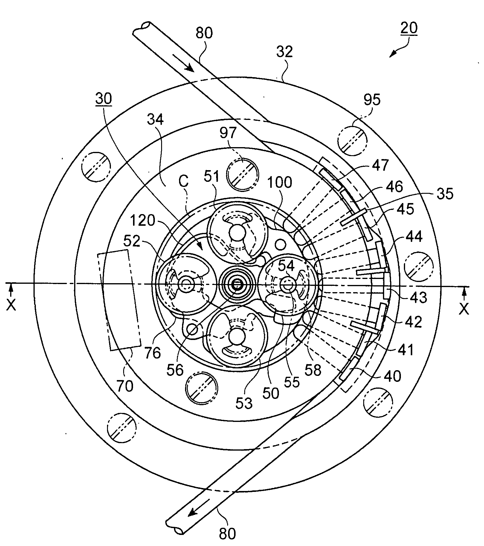
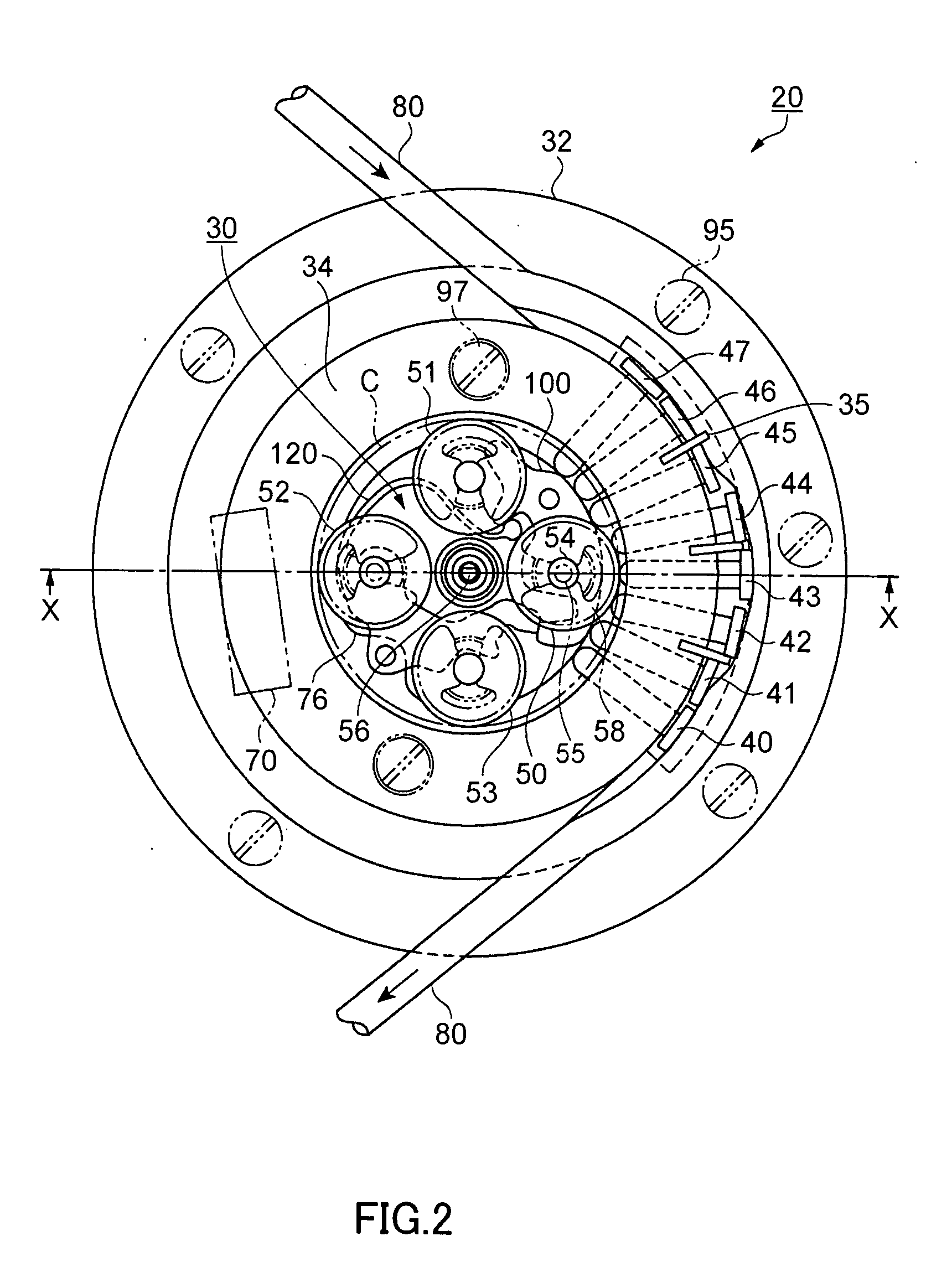
[0041]FIG. 1 to FIG. 8 show the fluid transporting device and the fluid transporter according to Mode of Embodiment 1.

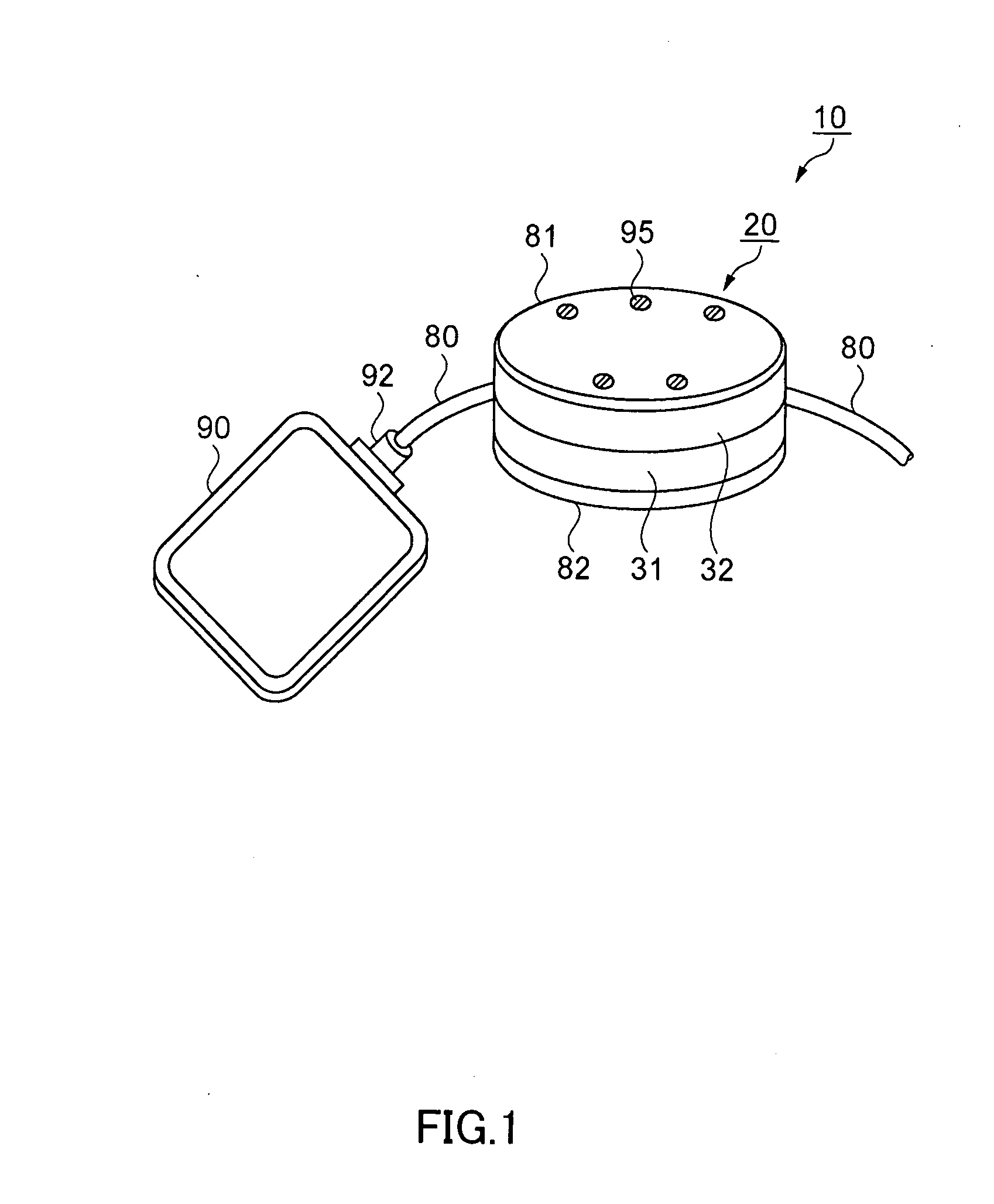
[0042]FIG. 1 is a perspective view showing a constitution of the fluid transporter of Mode of Embodiment 1. In FIG. 1, a fluid transporter 10 is constituted of a fluid transporting device 20 for transporting a fluid by writhing motions, and a pack-shaped fluid storing container 90 for storing the fluid. Moreover, the fluid transporting device 20 and the fluid storing container 90 are made to communicate with each other by a tube 80.

[0043]The fluid storing container 90 is made of a flexible synthetic resin and formed, in this mode of embodiment, of a silicone-family resin. The fluid storing container 90 is provided at its one end portion with a tube holding portion 92, in which the tube 80 is so hermetically fixed by removable connecting means such as a press fit or adhering means such as...

embodiment 2

[0109]According to Mode of Embodiment 2 thus far described, therefore, the rotary pressure mechanism 30 and the fluid storing portion 190 are arranged to have no overlap, so that the size can be reduced without increasing the thickness. Moreover, the casings for the rotary pressure mechanism 30 and the fluid storing portion 190 are formed into one, so that the cost can be reduced.

[0110]Moreover, the roller bed 76 can be rotated backward, as has been described in Mode of Embodiment 1, the fluid can be transported to the fluid storing portion 190 from the tank which is disposed outside of the fluid transporter 10. At this time, it is preferred that the fluid storing portion 190 is provided with an air communication hole.

[0111]Here, the invention should not be limited to the foregoing mode of embodiments, but could contain modifications and improvements within the scope to achieve the object of the invention.

[0112]In the aforementioned Mode of Embodiment 1, for example, the fluid flow ...


PUM


Abstract

A fluid transporting device comprises a tube frame having a tube guide wall for arranging a tube having an elasticity in an arcuate shape, and a rotary pressure mechanism having a plurality of rollers. The rotary pressure mechanism is arranged, when the tube is arranged in the tube frame, on the side opposite to the guide wall side of the tube, such that its center of rotation is aligned with the center of the arc of the tube guide wall. A plurality of push pins are interposed between the tube and the rotary pressure mechanism and are arranged radially of the center of rotation of the rotary pressure mechanism. A switching mechanism moves at least one of the rollers to a position for the push pins to release the tube and a position for the push pins to press the tube.

Description

TECHNICAL FIELD[0001]The present invention relates to a fluid transporting device and a fluid transporter provided with the fluid transporting device.BACKGROUND ART[0002]In the prior art, as a first conventional technique, there is known a tube pump (Japanese Patent No. 3,109,015) as a fluid transporting device comprising: a holder having an inner circumference formed into a generally arcuate shape; a tube having an elasticity and held in the inner circumference; a rotary disc having a groove so shaped as to hold at least one roller for elastically deforming and closing one portion of the held area of the tube and that the roller can move, when rotated in one direction, to a position to close the tube and, when rotated in the other direction, to a position to keep an elastic state without closing the tube; and a rubber plate so disposed at a position for the roller to start the push of the tube as intersects with the revolution path of the roller.[0003]As a second conventional techn...

Claims


Application Information

Patent Timeline
Patent Type & Authority Applications(United States)
IPC IPC(8): F04B43/12F04B43/09F04B45/067
CPCF04B43/082F04B43/1253F04B43/12
Inventor MIYAZAKI, HAJIMEKAWASUMI, KAZUOUSHIKOSHI, KENICHI
Owner SEIKO EPSON CORP
Why Eureka
Try Eureka