Fusion-bonded product having high-strength part and manufacturing method thereof

Inactive Publication Date: 2008-06-12
MUSA PRECISION IND
View PDF6 Cites 19 Cited by
  • Summary
  • Abstract
  • Description
  • Claims
  • Application Information

AI Technical Summary

Benefits of technology

[0026]According to the present invention, a required strength can be obtained by quenching the quenchable part (to be the high-strength part) of the second preparatory material. In addition, the first steel part of the first preform and the second steel part of the second preform are bonded by fusion welding. Thus, the second preparatory material does not fuse and harden at the bonded portion, whereby generation of a crack caused by the hardening of the bonded portion can be prevented. Namely, a required strength can be maintained at the bonded portion where the first preform and the second preform are bonded to each other. Further, since the fusion welding can be carried out under condition that the first preform and the second preform are fixed, it is easy to obtain a bonded product of a required precision. Moreover, the first material is formed by frictionally pressure-welding the second preparatory material containing not less than 0.60% of Carbon Equivalent and the first prepar

Problems solved by technology

In this case, there is a problem in that a required precision cannot be obtained in the bonded product that has been bonded by the friction pressure welding.
In order to accomplish the required precision in the bonded product that has been bonded by the friction pressure welding, the bonded product that has been bonded by the friction pressure welding has to be subjected to a machining process, which significantly increases a process cost.
However, since a ring gear requires a high strength, t

Method used


Image

  • Fusion-bonded product having high-strength part and manufacturing method thereof
  • Fusion-bonded product having high-strength part and manufacturing method thereof
  • Fusion-bonded product having high-strength part and manufacturing method thereof

Examples


Example

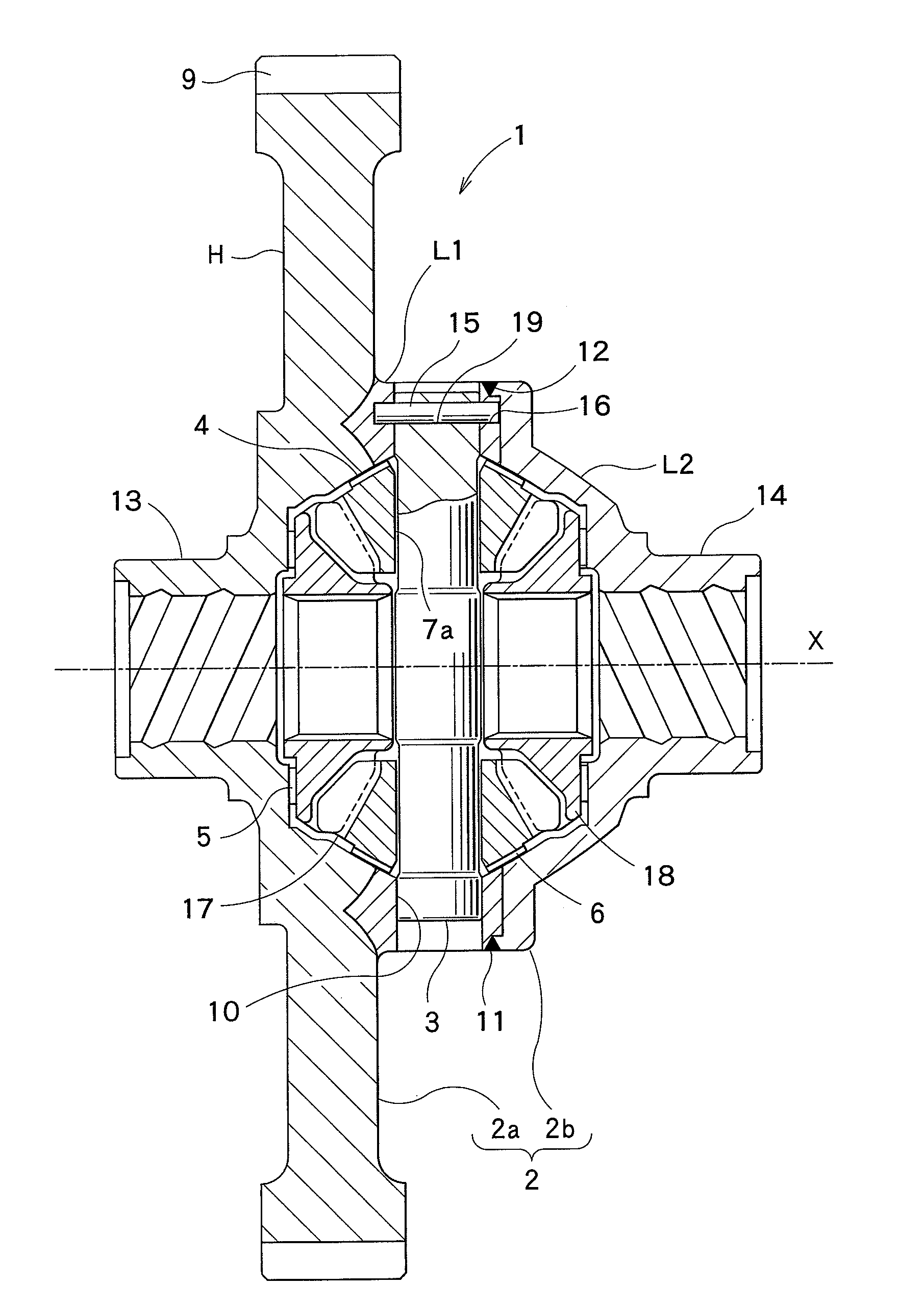
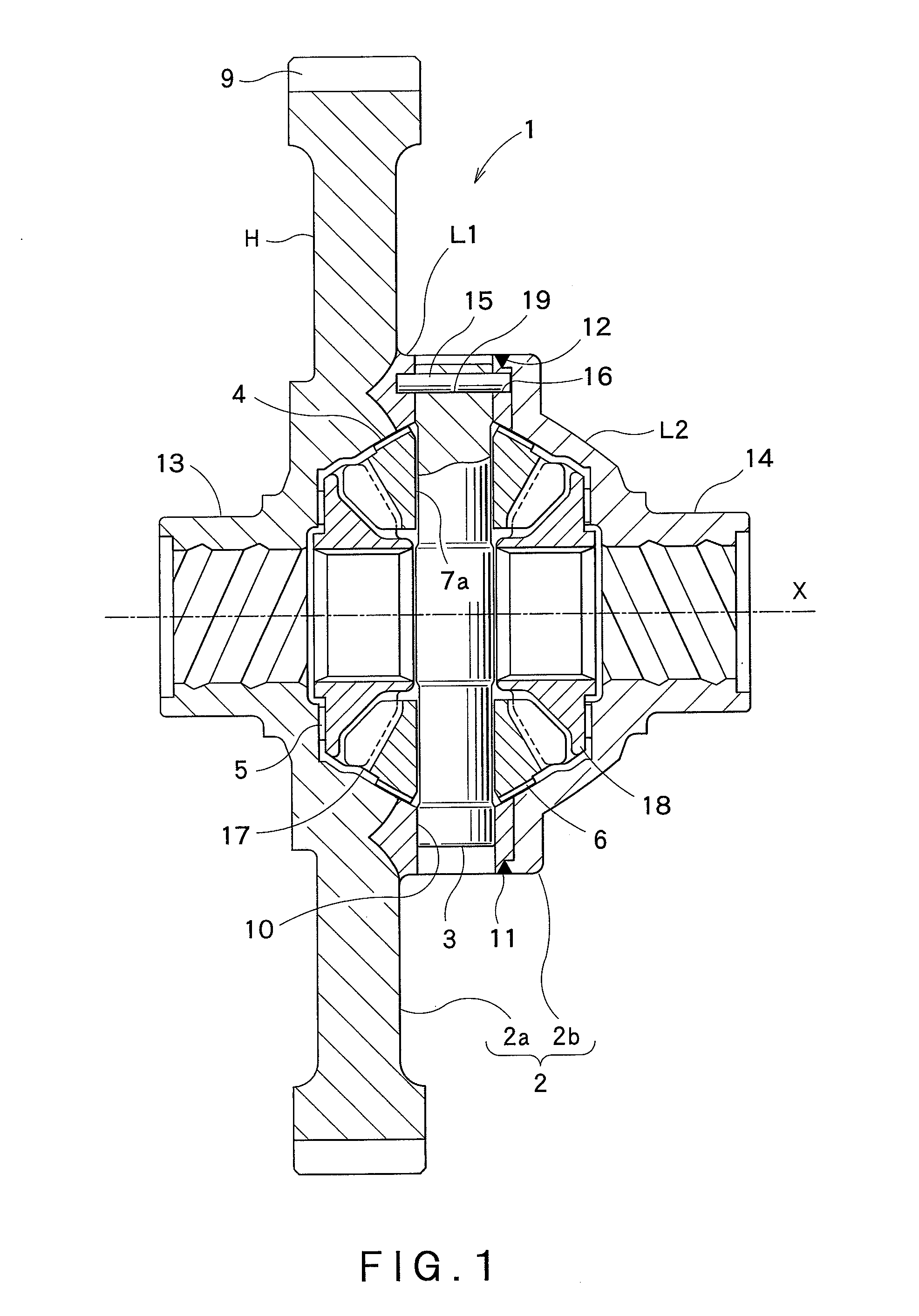
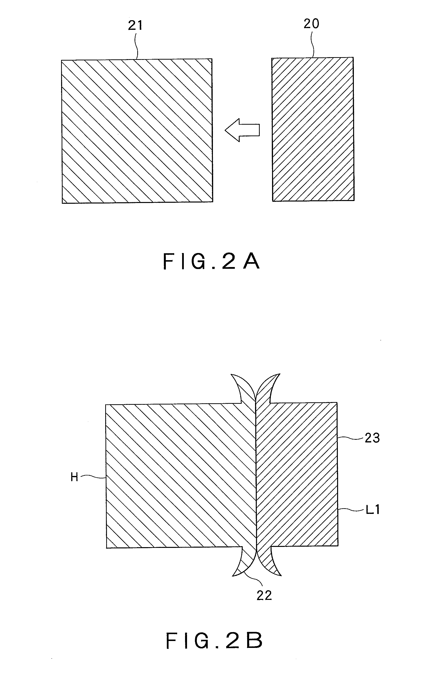
[0038]FIG. 1 is a sectional view of a differential case of a differential gear as a fusion-bonded product in one embodiment of the present invention. FIGS. 2A and 2B are sectional views illustrating a forming step of a first material, in a manufacturing method in one embodiment of the present invention. FIGS. 3A and 3B are sectional views illustrating a forming step of forming a first differential case from the first material, in the manufacturing method in one embodiment of the present invention. FIG. 4 is a sectional view of a first preform in the fusion-bonded product in one embodiment of the present invention. FIGS. 5A to 5C are sectional views illustrating a forming step of forming a second preform from a second material, in the manufacturing method in one embodiment of the present invention. FIG. 6 is a sectional view of the differential case, which is not yet welded, of the differential gear as the fusion-bonded product in one embodiment of the present invention.

[0039]At firs...


PUM

PropertyMeasurementUnit
Fractionaaaaaaaaaa
Fractionaaaaaaaaaa
Strengthaaaaaaaaaa

Abstract

The present invention is a fusion-bonded product having a high-strength part, comprising: a first preform (2a) constituted by integrally, frictionally pressure-welding a first low-carbon steel part (L1) made of low-carbon steel containing less than 0.45% of C and a high-carbon steel part (H) made of high-carbon steel containing not less than 0.45% of C; and a second preform (2b) having a second low-carbon steel part (L2) made of second low-carbon steel containing less than 0.45% of C; wherein the high-carbon steel part (H) of the first preform (2a) is provided with a high-strength part (9) that has been previously formed into a desired shape and quenched, the second low-carbon steel part (L2) of the second preform (2b) has been previously formed into a predetermined shape, and the first low-carbon steel part (L1) of the first preform (2a) and the second low-carbon steel part (L2) of the second preform (2b) are bonded to each other by fusion welding.

Description

CROSS REFERENCE TO RELATED APPLICATIONS[0001]This application is based upon the prior Japanese Patent Application No. 2006-331629 filed on Dec. 8, 2006 and the prior Japanese Patent Application No. 2007-315069 filed on Dec. 5, 2007, the entire contents of which are incorporated herein by reference.FIELD OF THE INVENTION[0002]The present invention relates to a fusion-bonded product having a high-strength part, and a manufacturing method thereof.BACKGROUND ART[0003]Friction pressure welding has been conventionally known as an art for bonding two members of different shapes to form a bonded product. For example, JP5-84614A discloses that a first preform and a second preform, which are provided with tooth profiles formed by precision forging, are bonded by friction pressure welding, so that a composite gear having a tooth profile part is formed.[0004]Laser welding has been known as another art for bonding two members of different shapes to form a bonded product. For example, JP2006-5091...

Claims


Application Information

Patent Timeline
IPC IPC(8): B32B15/01B23K20/12
CPCB23K15/0006B23K20/129Y10T428/12972Y10S475/901Y10T428/12965B32B15/011
Inventor MATAGA, AKIRAKUWANOTE, TAKASHI
Owner MUSA PRECISION IND
Why Eureka
Try Eureka