Fuel cell apparatus

Inactive Publication Date: 2008-06-12
CANON KK
View PDF4 Cites 22 Cited by
  • Summary
  • Abstract
  • Description
  • Claims
  • Application Information

AI Technical Summary

Benefits of technology

[0027]It is an object of the present invention to provide a fuel cell apparatus capable of performing stable power generation by ach

Problems solved by technology

On the other hand, in an atmosphere which is excessively humidified, an inside of a fuel cell unit is in an “excessively-humidified state”.
Accordingly, flow rates of the cooling gas and the oxidizer gas cannot be controlled independently of each other.
Further, in the related art distribute gas system, since the flow rates of the oxidizer gas and the cooling gas cannot be controlled independently of each other, the control of the temperature and the control of the humidity interfere with each other.
Accordingly, it is difficult to set an optimum driving state.
However, in the distribute gas system, there is a problem in that the increase in the flow rate of the cooling g

Method used


Image

  • Fuel cell apparatus
  • Fuel cell apparatus
  • Fuel cell apparatus

Examples


Example

[0040]Hereinafter, a description will be made of a fuel cell apparatus according to an embodiment of the present invention.

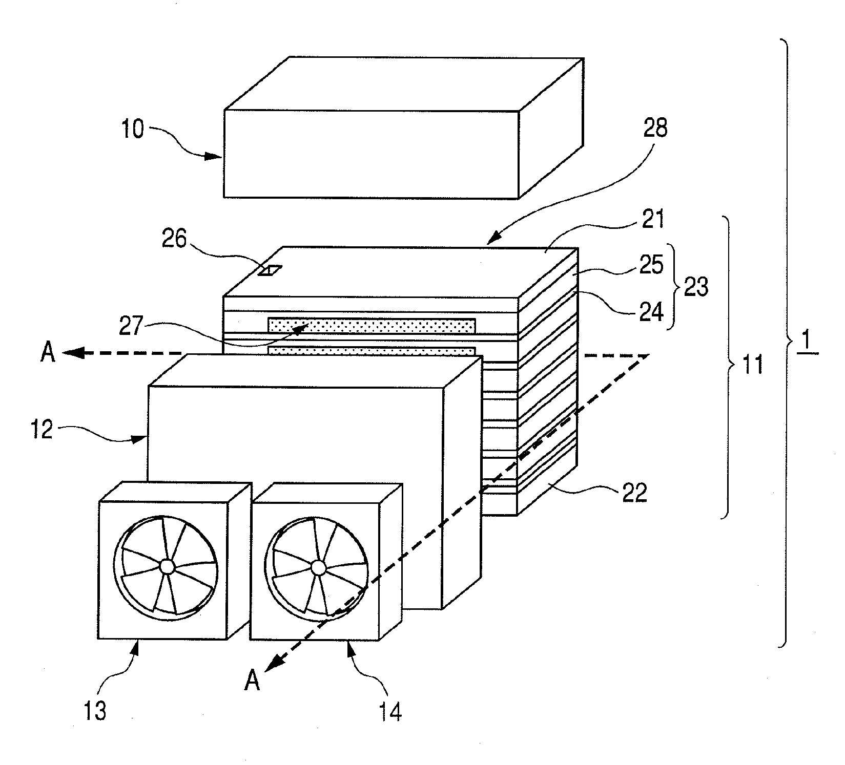
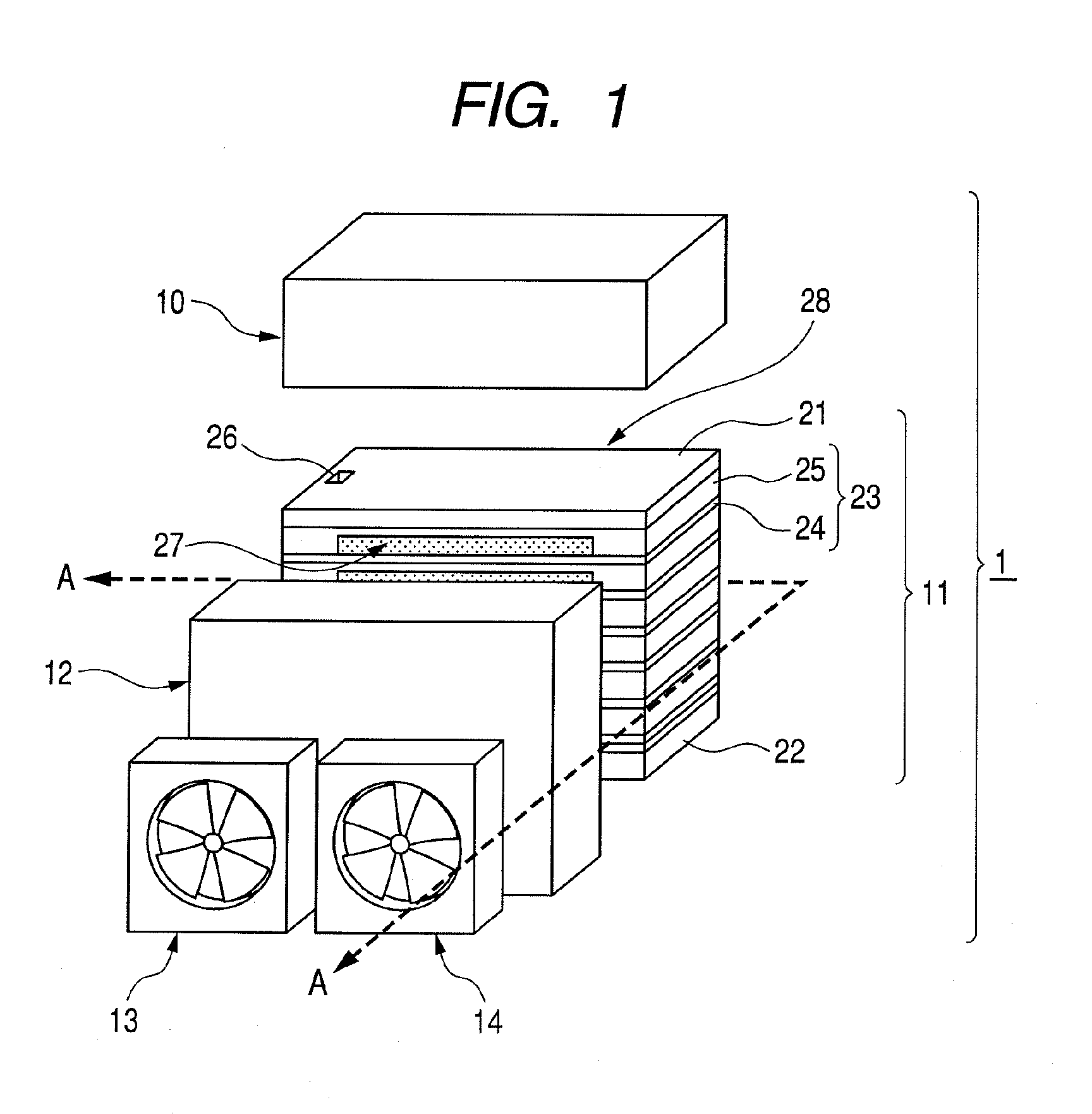
[0041]FIG. 1 is an exploded perspective view for describing the fuel cell apparatus according to this embodiment. There are provided a fuel cell apparatus 1, a fuel tank 10, a fuel cell stack 11, a manifold 12, a first blowing fan 13 serving as a first blowing unit, and a second blowing fan 14 serving as a second blowing unit.

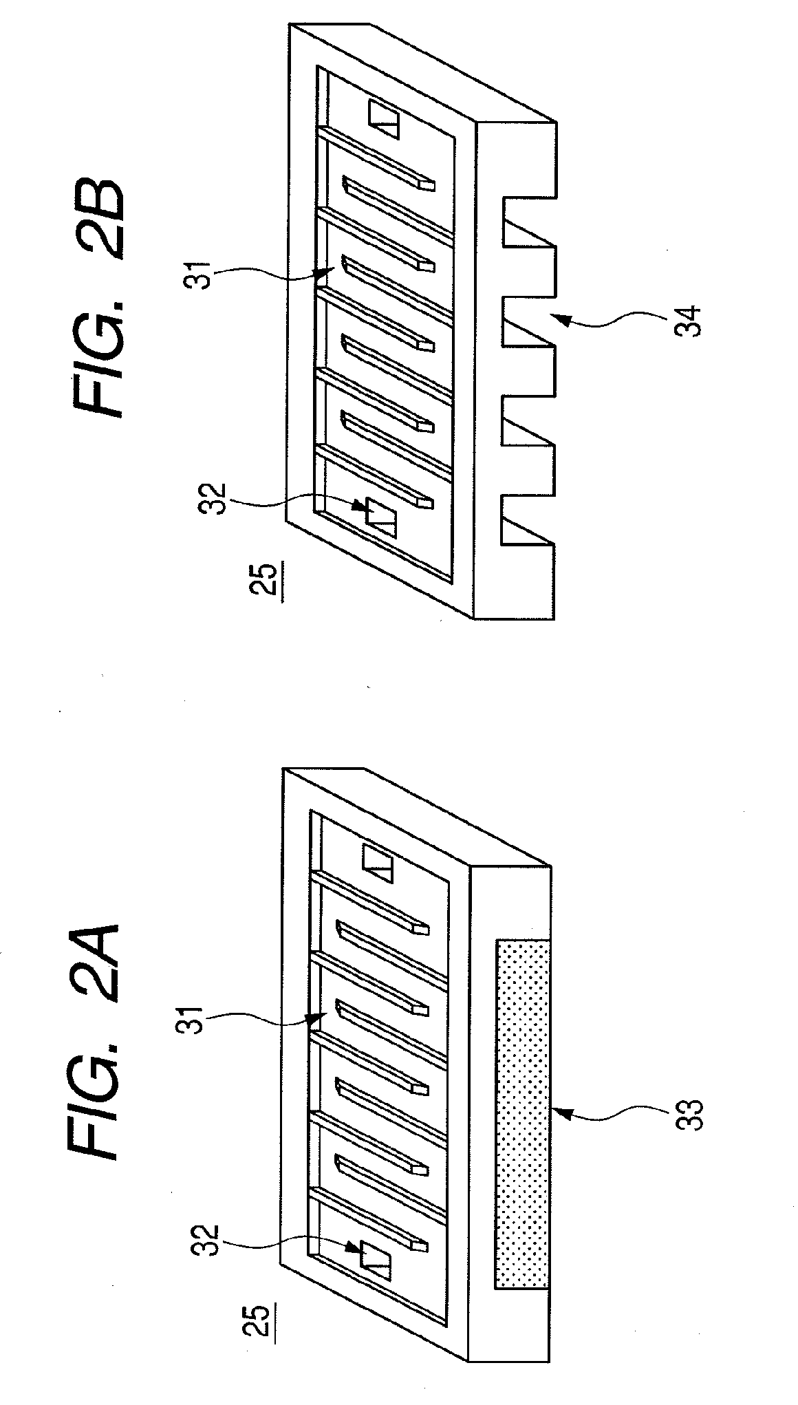
[0042]End plates are denoted by reference numerals 21 and 22, a fuel cell unit is denoted by reference numeral 23, membrane electrode assembly is denoted by reference numeral 24, a separator is denoted by reference numeral 25, and a fuel flow path inlet is denoted by reference numeral 26.

[0043]The fuel cell apparatus 1 of this embodiment includes the fuel tank 10, the fuel cell stack 11, the manifold 12, the first blowing fan 13 serving as the first blowing unit, and the second blowing fan 14 serving as the second blowing unit.

[0044]The fue...


PUM


Abstract

The present invention provides a fuel cell apparatus in which stable power generation can be performed by achieving both temperature control and humidity control with a simple structure, whereby enabling downsizing of the fuel cell apparatus. The fuel cell apparatus which uses air as an oxidizer includes: a fuel cell stack including multiple fuel cell units laminated to each other; an oxidizer flow path having a first opening portion and a second opening portion at both ends thereof, for supplying the air to the multiple fuel cell units; a manifold for covering at least a part of the first opening portion; a first blowing unit provided to the manifold, for ensuring an air amount required for power generation in the fuel cell stack; and a second blowing unit provided to the manifold, for controlling a humidity state of the fuel cell stack.

Description

BACKGROUND OF THE INVENTION[0001]1. Field of the Invention[0002]The present invention relates to a fuel cell apparatus, and more particularly, to a fuel cell apparatus in which both temperature control and humidity control are achieved.[0003]2. Description of the Related Art[0004]Fuel cell apparatuses are constructed so that a fuel gas and an oxidizer gas such as air are supplied thereto to perform power generation and have a potential for allowing a suppliable energy amount per volume to be several to ten times compared to a related art battery.[0005]Further, by being charged with a fuel, the fuel cell apparatuses enable long-term use of small electronic devices such as mobile phones and notebook personal computers, thereby being promising.[0006]Among the fuel cell apparatuses, a polymer electrolyte fuel cell includes a polymer electrolyte membrane and a pair of electrodes arranged on both surfaces of the polymer electrolyte membrane. The polymer electrolyte fuel cell can be used a...

Claims


Application Information

Patent Timeline
IPC IPC(8): H01M8/02
CPCH01M8/04007H01M8/04089H01M8/04119H01M8/0432Y02E60/50H01M8/04559H01M8/04753H01M8/04828H01M2008/1095H01M8/04492
Inventor MOGI, SATOSHI
Owner CANON KK
Why Eureka
Try Eureka