
Engine speed control for a low power hydromechanical transmission

a hydromechanical transmission and engine technology, applied in the direction of fluid couplings, gearings, instruments, etc., can solve the problems of engine torque absorption limited to a level typically less than, engine speed to vary beyond the range of belt cvt's, and the control algorithm of low-power hydromechanical transmissions (hmts) on small horsepower (50 hp) vehicles is lacking in responding to external loads and operator inputs in certain modes

Inactive Publication Date: 2008-06-12
DANFOSS POWER SOLUTIONS INC
View PDF47 Cites 135 Cited by
  • Summary
  • Abstract
  • Description
  • Claims
  • Application Information

AI Technical Summary

Benefits of technology

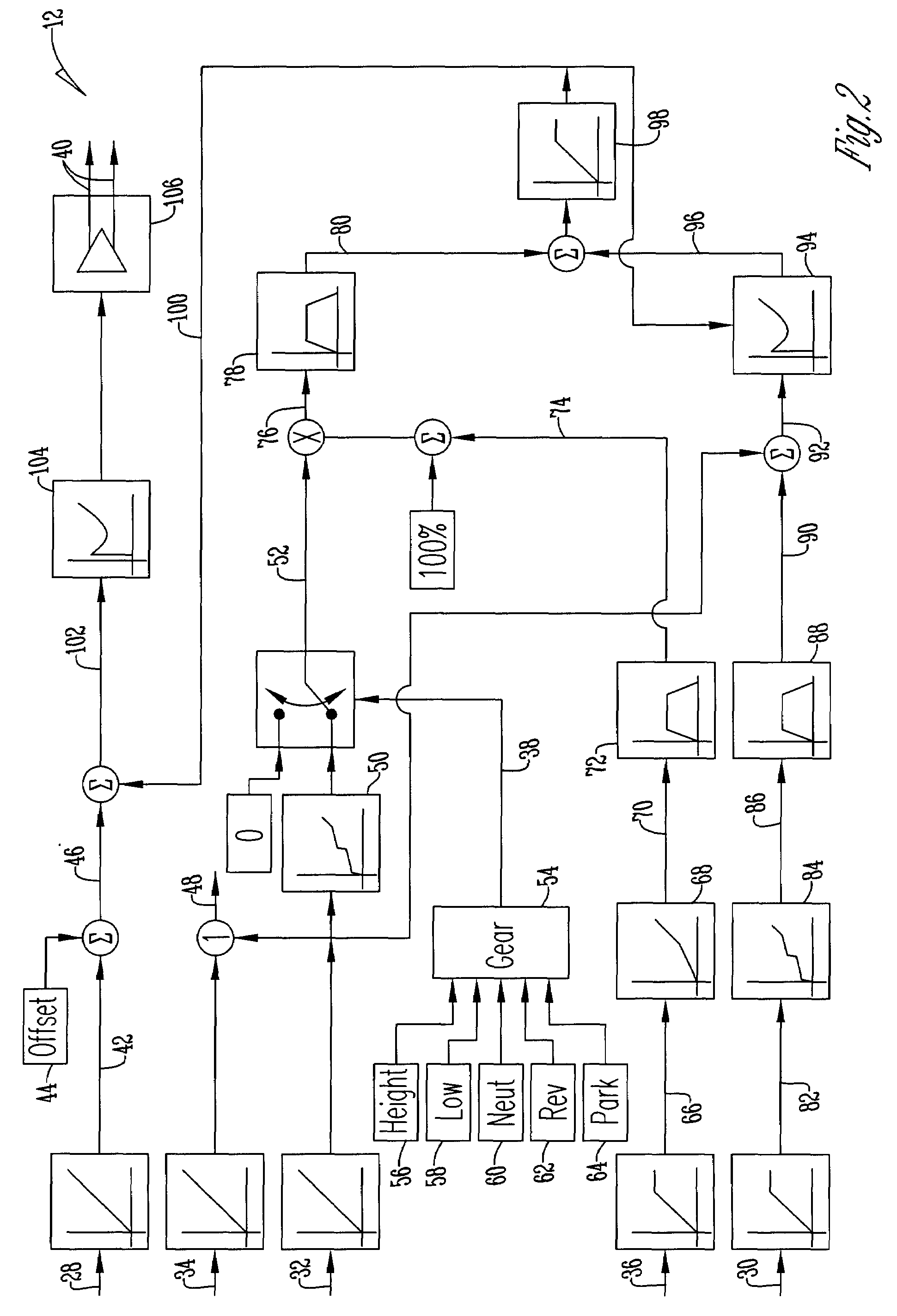
[0011]A method of operating a transmission. The method includes providing a controller that is able to receive a plurality of input signals including swashplate position, vehicle RPM, engine RPM, brake position, and throttle position signals. The controller then determines an open loop ratio percentage based upon the engine RPM signal and the brake signal by using a first algorithm while determining simultaneously a closed loop ratio percentage from the engine RPM signal, the vehicle RPM signal, and the throttle signal with a second algorithm. The first and second algorithms are then summed in order to calculate a ratio command percentage that is summed with a previously determined swashplate input to determine a swashplate error percentage. By using this swashplate error percentage and digital logic the controller is then able to actuate a swashplate positioner based upon the swashplate error percentage to operate the transmission.

Problems solved by technology

Previous Control Algorithms for low power hydromechanical transmissions (HMTs) on small horsepower (<50 Hp) vehicles have proven to be lacking in responding to external loads and operator inputs in certain modes.
However, when extreme external load variations occur the current HMT systems cause the engine speed to vary beyond those of belt CVT's.
Thus, the engine torque absorption is limited to a level typically less than 25% of accelerating torque for the same engine speed.
This results in engine speed staying high or over-speeding as the engine is unable to absorb all the torque at its output shaft.
Thus, present open loop control algorithm implementations require complicated logic to accomplish desired control with slow response resulting in delay of engine speed recovery during throttle reapplication.

Method used


Image

  • Engine speed control for a low power hydromechanical transmission
  • Engine speed control for a low power hydromechanical transmission
  • Engine speed control for a low power hydromechanical transmission

Examples


Embodiment Construction

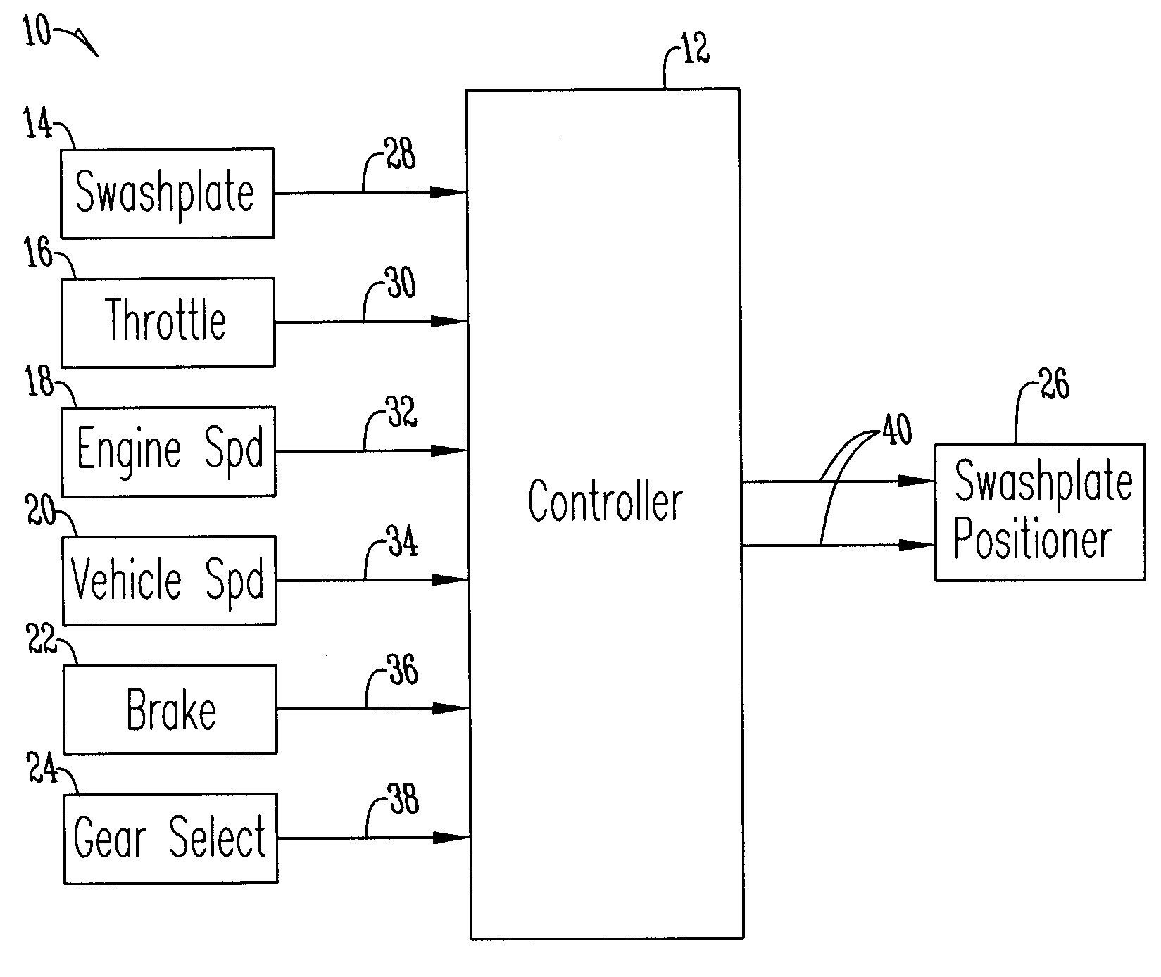
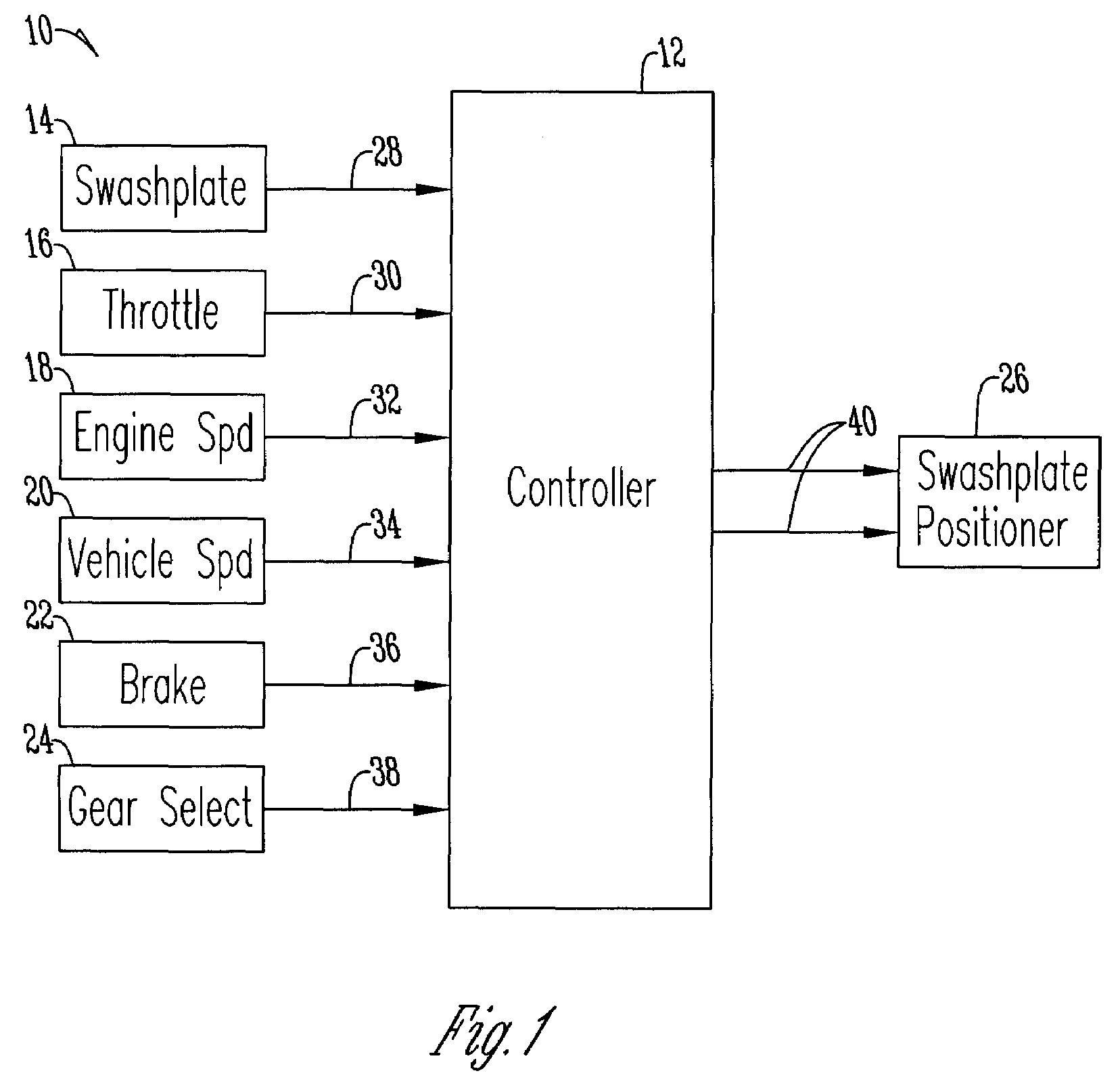
[0015]FIG. 1 shows and electronic transmission control system 10 having a controller 12 that receives a plurality of input signals from a swashplate sensor 14, a throttle sensor 16, an engine speed sensor 18, a vehicle speed sensor 20, a brake sensor 22, and a gear select sensor 24 to provide an output to a swashplate positioner 26. In one embodiment the swashplate positioner is a DC motor. For the purposes of this description the input signals are considered a swashplate input signal 28, a throttle input signal 30, an engine speed RPM input signal 32, a vehicle speed RPM input signal 34, a brake input signal 36, and a gear select signal 38 whereas the output signals are considered a control output signal 40.

[0016]FIG. 2 shows a schematic diagram of a first and second control algorithm used in combination with a swashplate input in order to provide the controller output signal 40. The swashplate input is created by providing the swashplate input signal 28 that the controller 12 is p...


PUM


Abstract

A method of operating a transmission of a vehicle. The method includes determining an open loop ratio percentage from an engine RPM input signal and a brake input signal using a first algorithm. Determining a closed loop ratio percentage from the engine RPM input signal, a vehicle RPM input signal and a throttle input signal using a second algorithm. Summing the open loop percentage and closed loop ratio percentage to calculate a ratio command percentage that is used to sum with a swashplate input to actuate a swashplate positioner and operate the transmission.

Description

BACKGROUND OF THE INVENTION[0001]This invention relates to an engine speed control. More specifically, this invention relates to a method of using a control algorithm to improve the operation of a transmission.[0002]Previous Control Algorithms for low power hydromechanical transmissions (HMTs) on small horsepower (<50 Hp) vehicles have proven to be lacking in responding to external loads and operator inputs in certain modes. These external loads include varying terrain, wheel slip conditions, and pulling loads. Operator inputs include throttle adjustments and braking changes. The goal for a control is for an operator to set a desired engine speed using the throttle and have the transmission control system adjust the transmission ratio to maintain that desired engine speed within limits as the external loading changes. When the vehicle speed is adjusted by the transmission ratio and does not match the desired vehicle speed for the operator, the operator must then make a manual adj...

Claims


Application Information

Patent Timeline
IPC IPC(8): B60W10/10G06F17/00F16H61/42F16H61/46F16H61/465
CPCF16H59/24Y10T477/631F16H59/44F16H59/54F16H61/42F16H61/465F16H2061/0078F16H2061/0096F16H2059/6853F16H2059/366Y10T477/6939Y10T477/69Y10T477/635Y10T477/688Y10T477/68F16H59/36
Inventor WILLIAMS, KEITH R.
Owner DANFOSS POWER SOLUTIONS INC
Learn More