Medical stent and devices for localized treatment of disease

Inactive Publication Date: 2008-06-12
KRAUSE ARTHUR A +1
View PDF48 Cites 36 Cited by
  • Summary
  • Abstract
  • Description
  • Claims
  • Application Information

AI Technical Summary

Benefits of technology

[0036]When the device is used to deliver a treatment agent such as a drug, medication or other treatment substance to the affected site, it can be coated with a non-toxic dissolvable material, such as sugar for example, that will prevent dissolution or loss of t

Problems solved by technology

However, a limitation associated with angioplasty is the abrupt closure of the vessel that may occur immediately after the procedure, and restenosis, which occurs gradually following the procedure and refers to the re-narrowing of an artery after an initially successful angioplasty.
Additionally, restenosis is a chronic problem in patients who have undergone saphenous vein bypass grafting.
Post-angioplasty closure of the vessel, both immediately after angioplasty (acute reocclusion) and in the long term (restenosis), is a major difficulty associated with angioplasty.
Because 30-50% of patients undergoing angioplasty will experience restenosis, the success of angioplasty alone is clearly limited as a therapeutic approach to coronary artery disease.
Stenting alone, however, may not always be successful because small m

Method used


Image

  • Medical stent and devices for localized treatment of disease
  • Medical stent and devices for localized treatment of disease
  • Medical stent and devices for localized treatment of disease

Examples


first embodiment

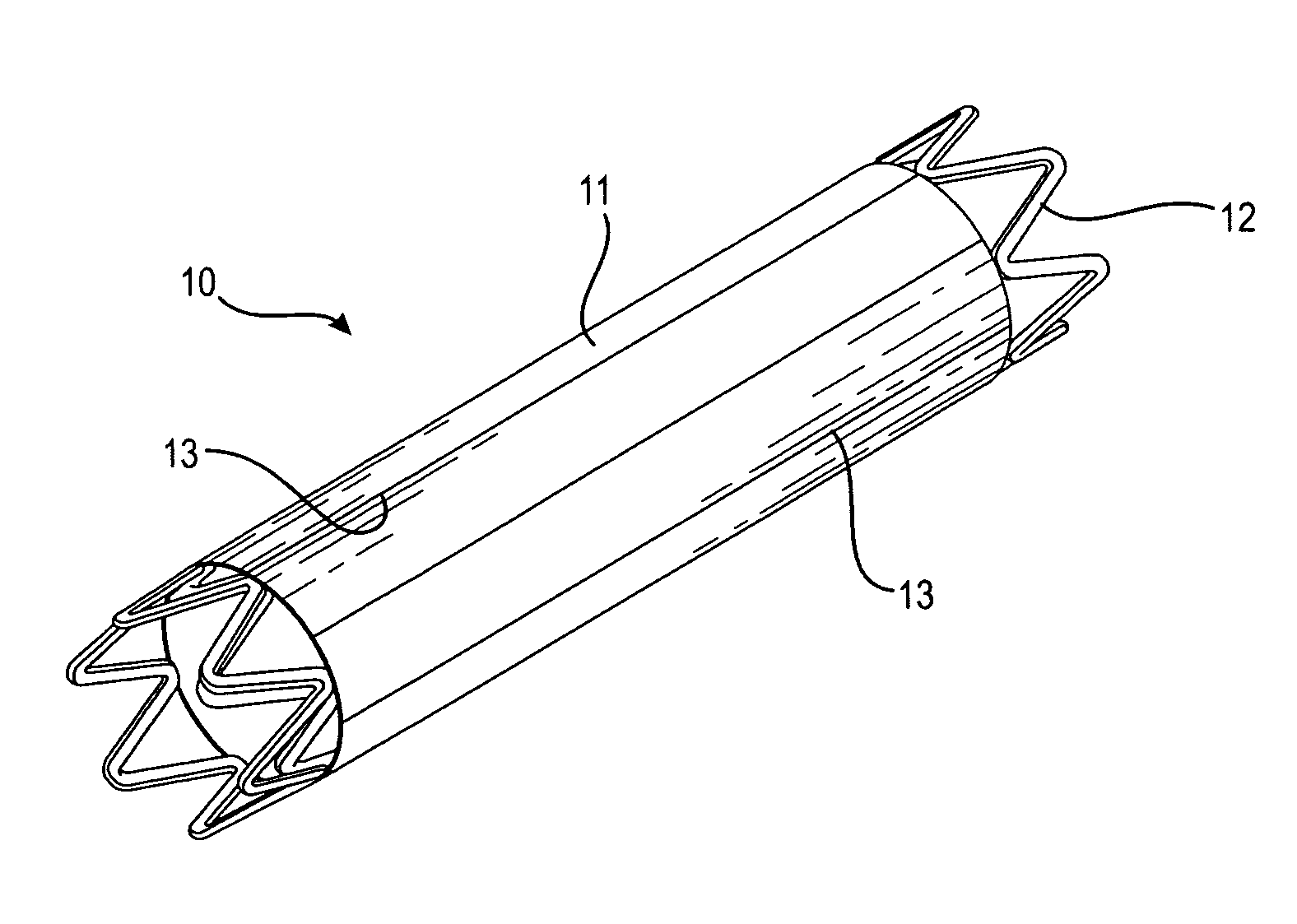
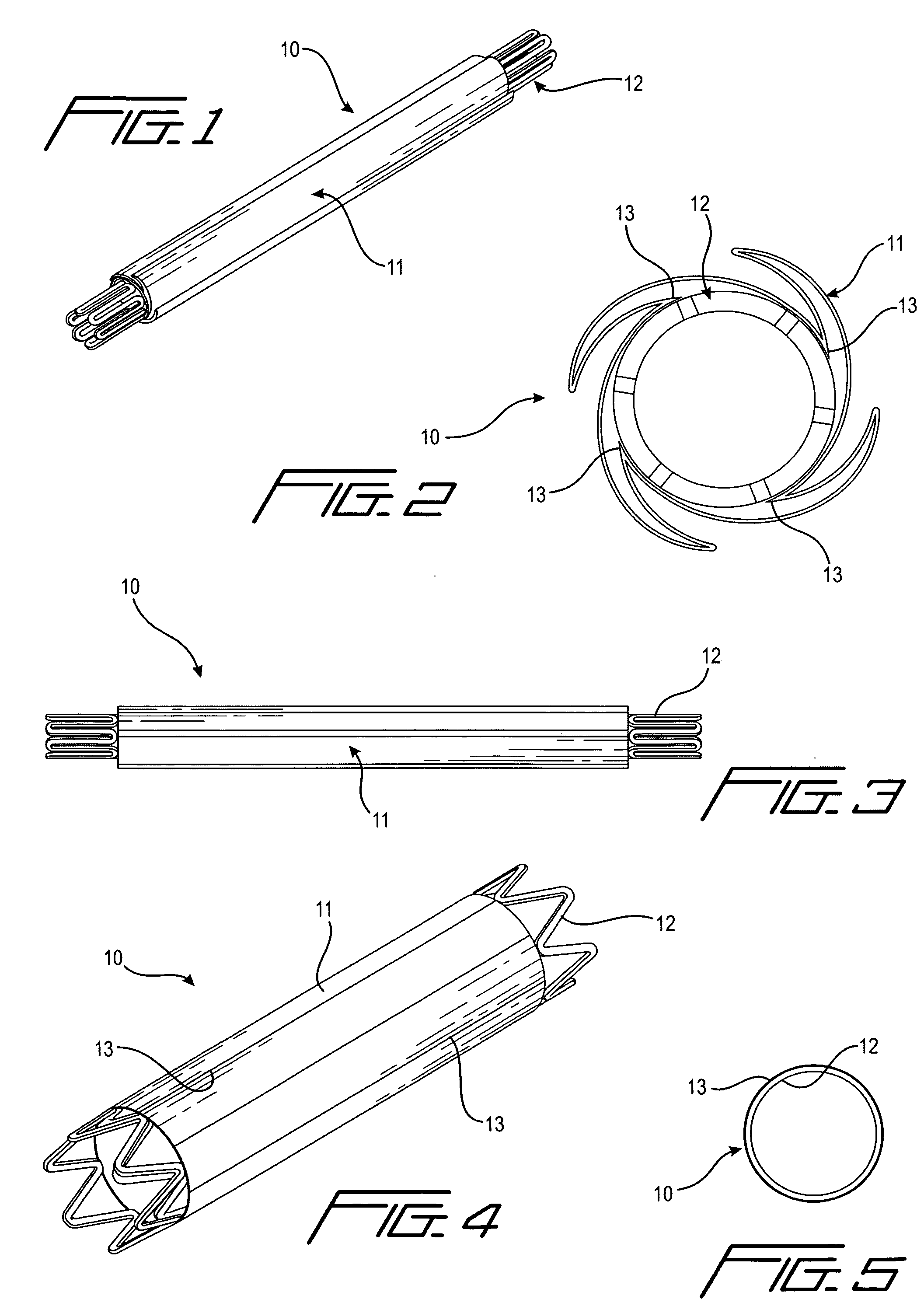
[0075]a stent with auxiliary structure according to a first aspect of the invention is shown generally at 10 in FIGS. 1-5. In this form, a longitudinally pleated cover 11 is attached to a stent body 12, which may be of any suitable conventional construction, at longitudinally extending points 13 (see FIG. 2). The cover is applied to the stent body while the stent is in its as-manufactured expanded condition (see FIG. 4), and is attached by welding or other suitable fastening means. The stent and cover are then collapsed to a contracted condition as shown in FIGS. 1-3.

second embodiment

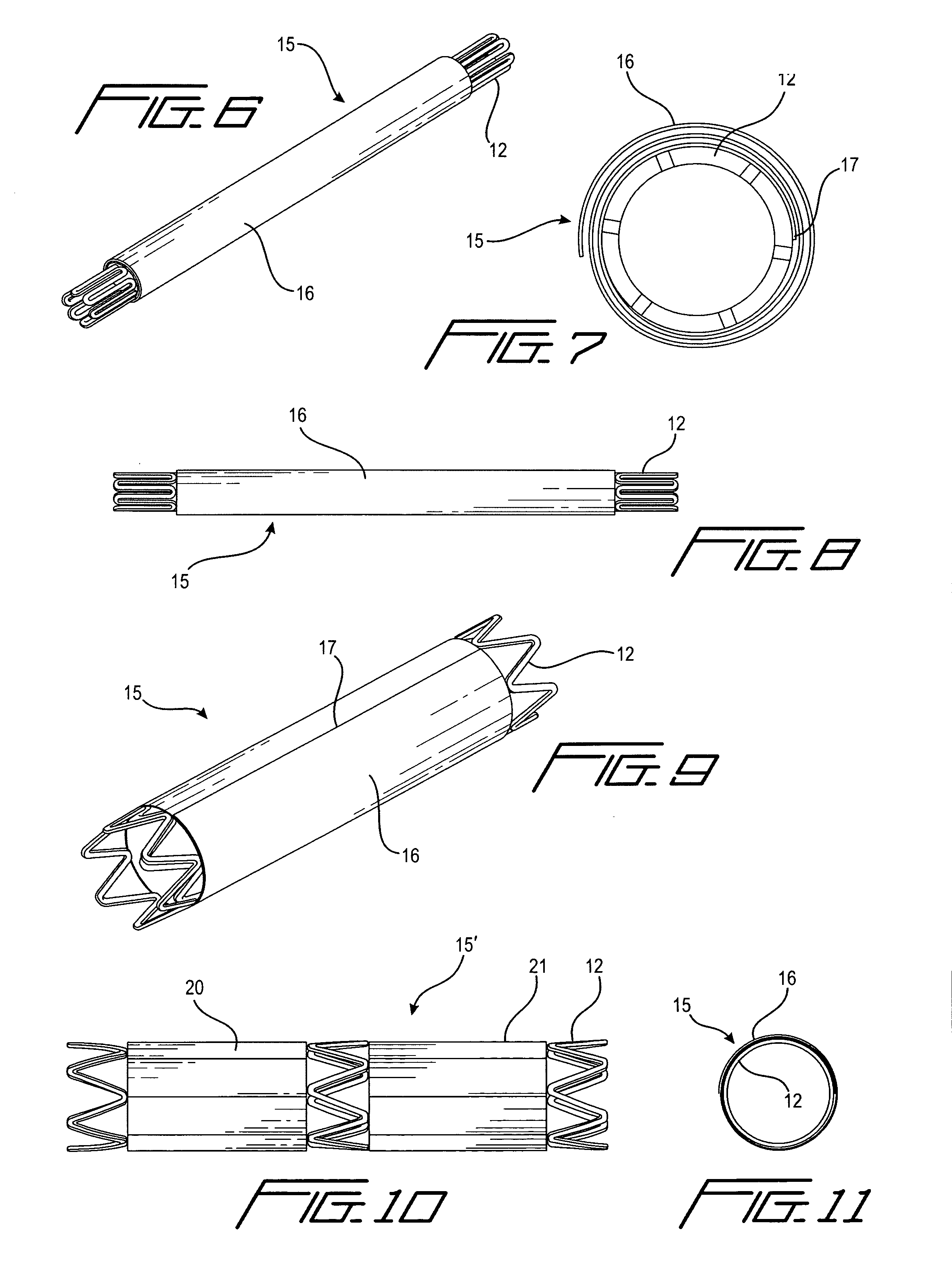
[0076]a stent with auxiliary structure according to the first aspect of the invention is shown generally at 15 in FIGS. 6-9 and 11. In this form, a coiled cover 16 is attached to the stent body 12 along one edge 17 extending longitudinally of the stent. The coiled cover is applied while the stent is in its as-manufactured expanded condition as shown in FIGS. 9 and 11, after which the stent is collapsed and the cover coiled around it as shown in FIGS. 6-8.

[0077]FIG. 10 depicts a variation 15′ of the forms of invention shown in FIGS. 1-9 and 11, in that a plurality of covers 20 and 21 are applied to the stent body in end-to-end relationship along the length of the stent. The covers may be longitudinally pleated as in FIG. 1, or coiled as in FIG. 6.

third embodiment

[0078]the first aspect of the invention is indicated generally at 25 in FIGS. 12-14. In this embodiment, the cover 26 comprises a plurality of overlapping plates 27, 28, 29, fixed by any suitable means, such as by welding, at an upstream end 30 to the stent body 12 and left unattached over the rest of their length. The plates are attached to the stent body while the stent is in its expanded, as-manufactured condition, at which time the plates 27, 28, 29 preferably will not be overlapping, as depicted in FIG. 14. After the plates are attached, the stent and cover are collapsed to their contracted condition as depicted in FIGS. 12 and 13. The plates may be suitably treated, as by texturizing their surface (not shown), or providing depressions or holes 31 therein (FIG. 15), or providing a polymer coating, to hold a drug or drugs applied to the plates.


PUM


Abstract

A medical device for treatment of a stenosed body lumen includes an open-ended cylindrical body movable between a collapsed position and a radially expanded position pressed against the wall of the lumen is carried on a distal end of a catheter for insertion of the device into the lumen and placement at the stenosed site. In one embodiment the body sidewall is an open lattice-like structure, and a cover is attached to its outer surface. In another embodiment, concentric laminated tubes of dissimilar materials, such as, e.g., copper and silver, form the body. In a further embodiment stacked rings of different materials form the body. In a still further embodiment the device is temporarily placed in a body lumen for treatment of a stenosed site, after which the device is withdrawn. In all forms the body may have an outwardly flared inlet end to reduce turbulence.

Description

[0001]This application claims the benefit of U.S. provisional patent application Ser. No. 60 / 852,597, filed Oct. 18, 2006.TECHNICAL FIELD[0002]The present invention relates to medical devices. In particular, the present invention relates to stents for placement in a body lumen to correct or treat a diseased area in the lumen, as well as to devices for treatment of sites in a lumen that have been previously stented or previously unstented, and to devices for localized treatment of other diseased tissue.BACKGROUND ART[0003]Diseased tissue generally is treated with surgical intervention, or drug therapy, or a combination of both. The therapeutic alternatives available for treatment of vascular disease, for example, which is caused by progressive blockage, or stenosis, of the blood vessels that perfuse the heart and other major organs, normally include surgical intervention to remove the blockage, i.e., replacement of the blocked segment with a new segment of artery, or the use of a cat...

Claims


Application Information

Patent Timeline
IPC IPC(8): A61F2/84A61F2/82A61F2/06
CPCA61F2/07A61F2/88A61F2/91A61F2/915A61F2002/068A61F2002/9155A61F2230/0054A61F2250/0068A61M2025/0057A61M2025/1095A61F2/89A61F2002/075A61F2220/0058A61F2250/0014
Inventor KRAUSE, ARTHUR A.LIM, WALTER K.
Owner KRAUSE ARTHUR A
Why Eureka
Try Eureka