
Total engine smart indicator for an aircraft, and application thereof

a technology of smart indicators and aircraft, applied in the field of engine instrumentation, can solve the problems of aircrew operating aircraft in unsafe manner, increased cockpit workload and aircrew stress, and particularly challenging tasks, so as to improve aircrew situational awareness and flight safety, and reduce cockpit workload

Inactive Publication Date: 2008-06-12
HOWELL INSTR
View PDF23 Cites 14 Cited by
  • Summary
  • Abstract
  • Description
  • Claims
  • Application Information

AI Technical Summary

Benefits of technology

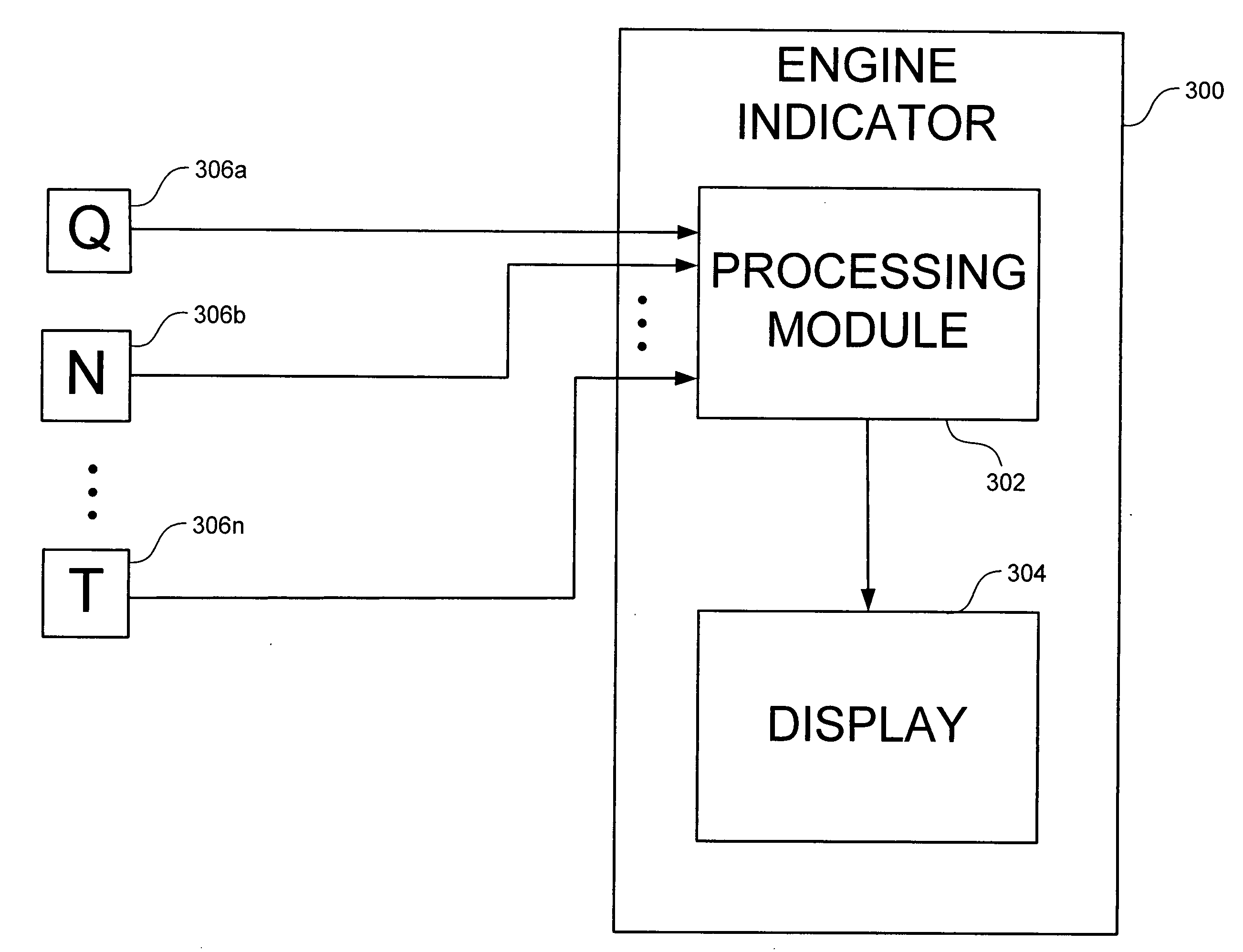
[0008]In an embodiment, where the indicator is installed in a cockpit of an aircraft, the indicator display automatically switches from one configuration to another configuration according to the type of engine being monitored and a particular phase of flight of the aircraft such as, for example, engine start-up, engine idle, aircraft take-off, aircraft cruse, and aircraft landing. It is a feature of the present invention that it enhances aircrew situational awareness and flight safety while reducing aircrew cockpit workload.

Problems solved by technology

This task is particularly challenging when, for example, during flight operations an aircrew is directed to change its mission.
This leads to increased cockpit workload and aircrew stress and may result in evaluation errors that can cause the aircrew to operate the aircraft in an unsafe manner.
Such errors are particularly critical when evaluating a rotary wing aircraft's performance and capabilities and can quickly lead to the loss of the aircraft and the aircrew.

Method used


Image

  • Total engine smart indicator for an aircraft, and application thereof
  • Total engine smart indicator for an aircraft, and application thereof
  • Total engine smart indicator for an aircraft, and application thereof

Examples


Embodiment Construction

[0023]The present invention provides a smart indicator for an engine, and applications thereof. In the detailed description of the invention that follows, references to “one embodiment”, “an embodiment”, “an example embodiment”, etc., indicate that the embodiment described may include a particular feature, structure, or characteristic, but every embodiment may not necessarily include the particular feature, structure, or characteristic. Moreover, such phrases are not necessarily referring to the same embodiment. Further, when a particular feature, structure, or characteristic is described in connection with an embodiment, it is submitted that it is within the knowledge of one skilled iri the art to affect such feature, structure, or characteristic in connection with other embodiments whether or not explicitly described.

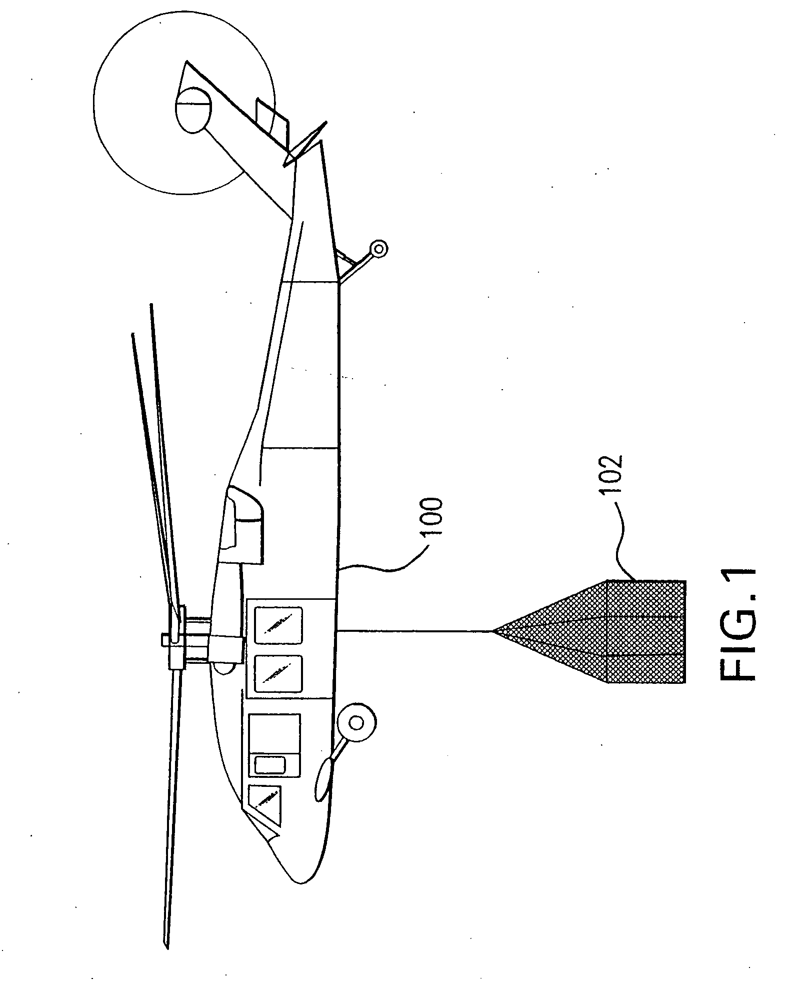
[0024]FIG. 1 is a diagram of an example aircraft 100 in which the present invention may be used. Aircraft 100 is a rotary wing aircraft capable of lifting and transpo...


PUM


Abstract

A smart indicator for an engine, and applications thereof. In an embodiment, the indicator includes a processing module and a display. The processing module receives a plurality of input parameter signals from various engine sensors. The input parameter signals are transformed by the processing module into values that can be displayed on the display. The display depicts at least the most relevant transformed value for controlling the engine and how this transformed value relates to an associated limit value for the engine such as, for example, a temperature limit value, a rotational speed limit value, or a torque limit value. In one embodiment, the input parameter signals are transformed by converting the input parameter signals to a plurality of digital values, subtracting an appropriate limit value for the engine from each digital value, dividing each resulting difference value by the appropriate limit value for the engine, and multiplying the resulting quotient value by a scaling value.

Description

FIELD OF THE INVENTION[0001]The present invention relates to engine instrumentation. More particularly, it relates to aircraft engine instrumentation.BACKGROUND OF THE INVENTION[0002]The performance and capabilities of an aircraft are dependent on the performance and capabilities of its engine(s). Thus, it is vitally important that aircrew members evaluate engine performance and capabilities during flight operations in order to ensure continued safe operation of the aircraft.[0003]Conventional engine instrumentation for an aircraft requires aircrew members to scan and monitor multiple indicators for each engine to verify that the engines are not exceeding a limit value that will effect continued safe operation of the aircraft. This task is particularly challenging when, for example, during flight operations an aircrew is directed to change its mission. A change in mission during flight operations requires aircrew members to re-evaluate the performance and capabilities of the aircraf...

Claims


Application Information

Patent Timeline
IPC IPC(8): G06F19/00
CPCG01D7/00G01D2207/10
Inventor TODINI, LUIGI
Owner HOWELL INSTR
Learn More