Robotic system for forming features in orthodontic aligners

a robot and orthodontic technology, applied in the field of orthodontics, can solve the problems of bad taste and discomfort, orthodontist's role in such a treatment regime, and the difficulty of rectification of undesired rotation of teeth,

Active Publication Date: 2008-06-19
HILLIARD JACK KEITH
View PDF32 Cites 128 Cited by
  • Summary
  • Abstract
  • Description
  • Claims
  • Application Information

AI Technical Summary

Benefits of technology

[0047]This invention provides a robotic system for forming features in orthodontic aligners. A selected region of an aligner is heated above its thermoforming temperature by a heating station (e.g., a laser, hot air pencil, or electrically-heated die). The heated region can then be manipulated by a thermoforming station to create a desired feature in the aligner. A laser station can also be used to trim excess material from the aligner or to cut features into the aligner or create identifying markings.
[0048]These and other advantages, features, and objects of the present invention will be more readily understood in view of the following detailed description and the drawings.

Problems solved by technology

Based primarily on U.S. Pat. No. 2,531,222, Kesling's tooth positioner was a bulky solid mass of vulcanized rubber that earned a reputation as being bad tasting and uncomfortable.
A problem faced by U.S. orthodontists in many states involves the requirement that stone models of a patient's teeth be physically stored for a period of years after the active phase of treatment ends.
Doctors usually view storing many hundreds of their patient's models as a challenge, requiring storage space and record keeping.
The orthodontist's role in such a treatment regime is limited to monitoring the progress of the aligner-based treatment and to take steps if required to insure that treatment progresses steadily toward the finished result according to the treatment plan.
The problem is the difficulty typically encountered in correcting an undesirably rotated tooth.
Normally, the positional bias or slight out-of-register relationship between an aligner's tooth-receiving compartment and the living tooth will produce force vectors that are capable of achieving certain types of correction, but correcting undesirable rotations is more difficult.
If inadvertent tooth contact occurs, undesirable or unintended tooth movement can result.

Method used


Image

  • Robotic system for forming features in orthodontic aligners
  • Robotic system for forming features in orthodontic aligners
  • Robotic system for forming features in orthodontic aligners

Examples


Embodiment Construction

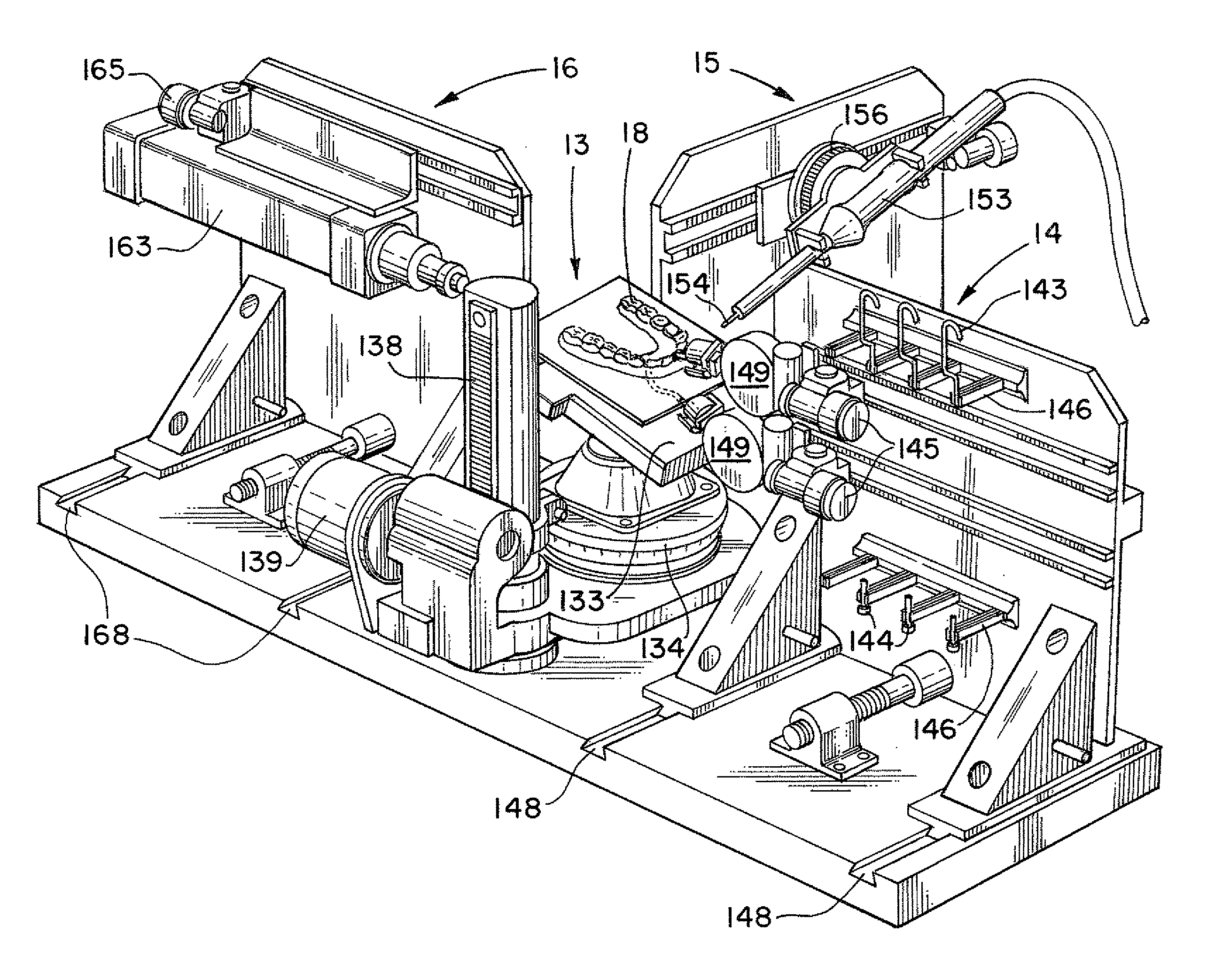
[0066]The present invention provides a robotic system 9 for use in modifying and forming features in conventional polymeric shell aligners. A block diagram of the present system is shown in FIG. 6. The major mechanical components of the robotic system 9 are a centrally-located turntable and lift platen 13 that provides three-dimensional positioning of an aligner 18, and a number of robotic stations 14, 15, and 16 arranged about the platen 13 for performing actions to form features on the aligner 18 and to trim away excess material. All of these mechanical components are under the control of a control system 8. For example, the stations can include at least one heating station 15, 16 for heating a selected small region of an aligner above the thermoforming temperature of the aligner material, and at least one thermoforming station 14 for manipulating the heated region to form a desired feature in the aligner 18. The control system 8 is typically implemented on a conventional computer...


PUM

PropertyMeasurementUnit
temperaturesaaaaaaaaaa
3D imagingaaaaaaaaaa
sizeaaaaaaaaaa

Abstract

A robotic system for forming features in orthodontic aligners includes a control system, a platen for three-dimensional positioning of the aligner, a heating station for selectively heating a small region of the aligner, and a thermoforming station for manipulating the heated region to form a desired feature in the aligner. Optionally, a laser cutting and trimming station can also be included to trim excess material from the aligner or to cut features into the aligner. The control system can include a processor with CAD software to enable a user to design features for aligners.

Description

RELATED APPLICATION[0001]The present application is based on and claims priority to the Applicant's U.S. Provisional Patent Application 60 / 870,696, entitled “Robotic System For Forming Features in Orthodontic Aligners,” filed on Dec. 19, 2006.BACKGROUND OF THE INVENTION[0002]1. Field of the Invention[0003]The present invention relates generally to the field of orthodontics. More specifically, the present invention discloses a robotic system for forming features in orthodontic aligners.[0004]2. Prior Art[0005]The present invention involves the convergence of multiple technologies that in combination present a novel mechanical system for robotically fabricating a type of orthodontic appliance known as a polymeric shell aligner. The present invention represents integration of certain 3D imaging and digital processes into a popular method of orthodontic treatment based on such aligners. The multiple technologies involved in the present invention include digital technologies that have be...

Claims


Application Information

Patent Timeline
Patent Type & Authority Applications(United States)
IPC IPC(8): A61C7/02
CPCA61C7/002A61C7/02A61C7/08Y10T29/5182Y10T29/5136Y10T29/49568A61C13/0027B23P23/00
Inventor HILLIARD, JACK KEITH
Owner HILLIARD JACK KEITH
Why Eureka
Try Eureka