Pedestal Head

a technology of pedestal and splint, which is applied in the field of pedestal heads, can solve the problems of difficult assembly, difficult installation of panels, and difficulty in malting lining up, and achieve the effect of improving the access floor panel system

Active Publication Date: 2008-06-19
KINGSPAN HLDG (IRL) LTD
View PDF10 Cites 26 Cited by
  • Summary
  • Abstract
  • Description
  • Claims
  • Application Information

AI Technical Summary

Benefits of technology

[0009]It is an object of this invention to provide an improved access floor panel syste

Problems solved by technology

Such prior art system has a number of drawbacks including:1. the lining up of the hole in the panel with the hole in the pedestal must be done by eye by trial and error since the panel covers up the threaded hole in the pedestal, thus malting lining up difficult, and assembly time consuming and

Method used


Image

  • Pedestal Head
  • Pedestal Head
  • Pedestal Head

Examples


Embodiment Construction

[0057]In the description that follows, like parts are marked in some cases with the same respective reference numerals. The drawings are not necessarily to scale and in some instances proportions may have been exaggerated in order to more clearly depict certain features of the invention.

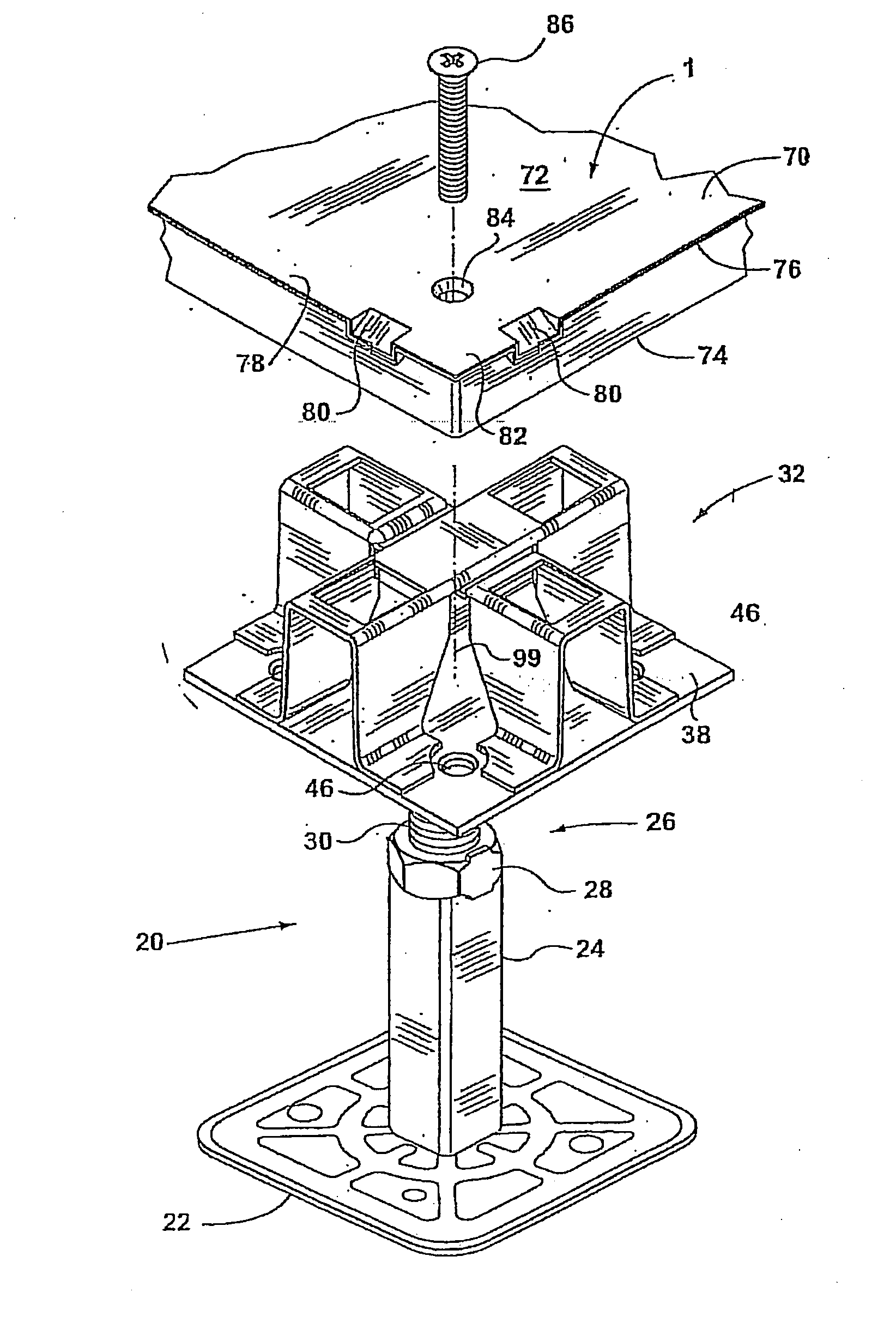
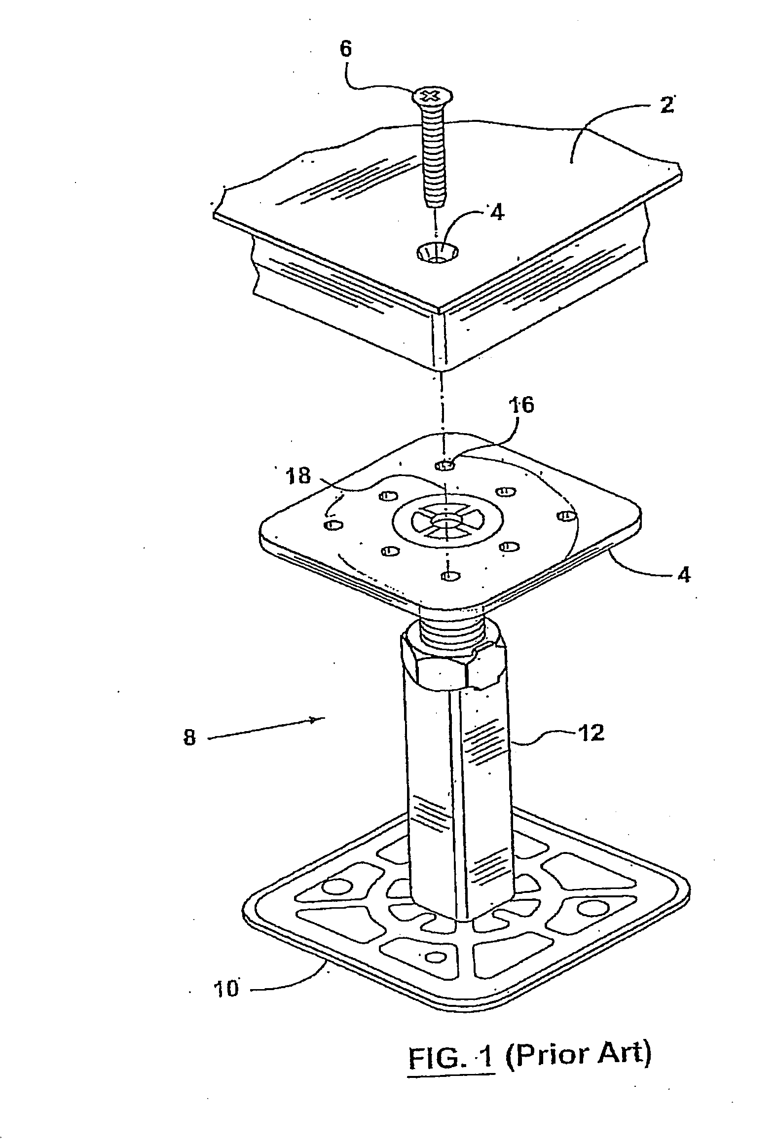
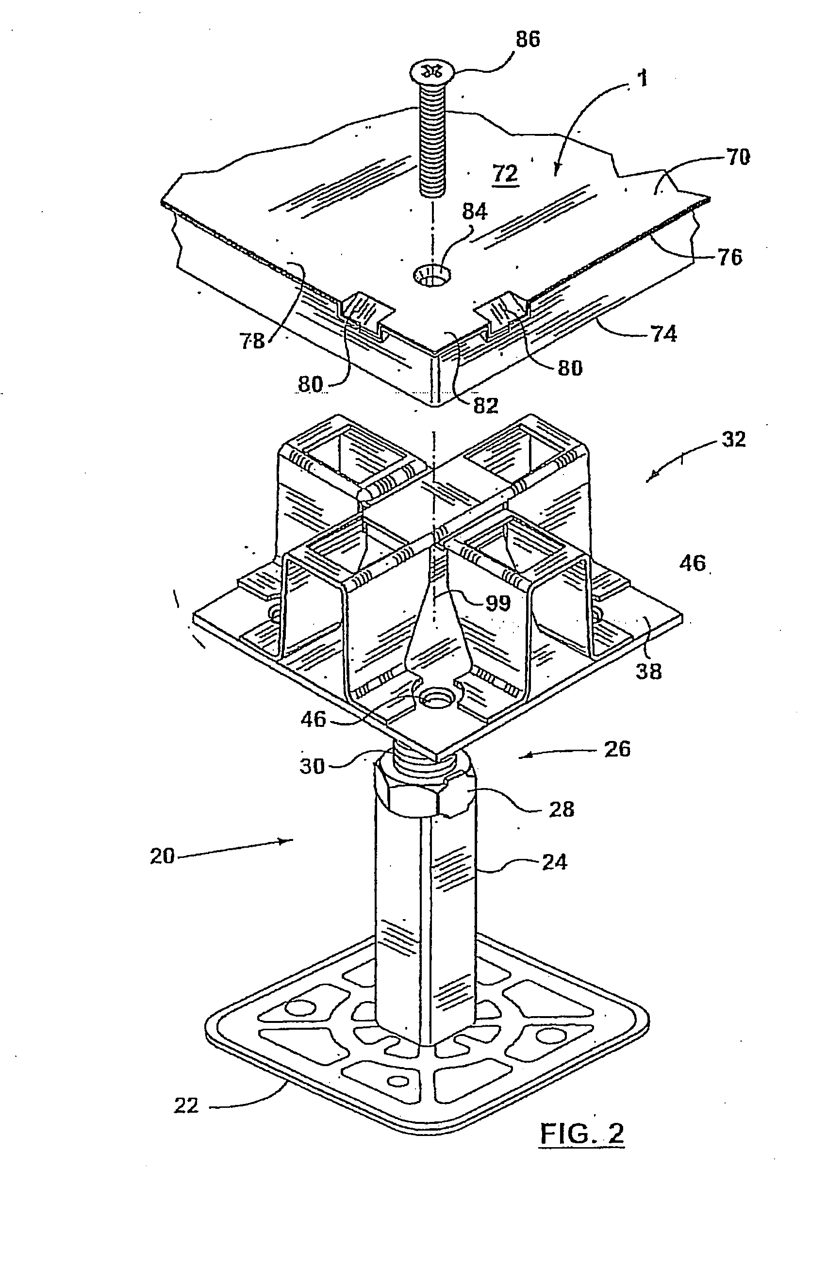
[0058]FIG. 1 illustrates an example of a prior art pedestal assembly for an access floor system. Generally speaking prior devices include a floor panel 2 having a hole 4 disposed in one corner of the panel tube for receiving a fastener 6. The panel 2 is adapted to rest on top of a flat plate 4 of a pedestal 8 which has a lower end 10 adapted to rest on a surface or sub-floor. The pedestal 8 generally includes an adjustable means which as shown comprises a nut and threaded shaft. Pedestal head base 4 includes a plurality of threaded holes 16 which must coaxially align with the hole 4 and fastener 6. As previously described the drawbacks of the prior art device include:[0059]1. the difficulty in lining...


PUM


Abstract

A pedestal head 100 for a floor panel 101 comprises a base 110 for a lower part of a floor panel 101 and an upper support 111 for receiving an upper part 107 of a floor panel 101. The pedestal head 100 has a receiver or projection 118 for receiving and locating a corresponding projection or receiver 105 of the floor panel 101. The pedestal head 100 may be die formed from a single piece of metal.

Description

FIELD OF THE INVENTION[0001]This invention relates to pedestal heads for locating and fastening a raised floor panel thereto, and includes methods of locating and fastening an access floor panel to a pedestal.BACKGROUND OF THE INVENTION[0002]Raised access floor panels are widely used. Generally speaking, such access floor panels are located and attached to a flat plate presented at the upper end of a pedestal as generally illustrated in the prior art drawing of FIG. 1. The panel in the prior art drawing generally utilizes a flat head bolt which is disposed through a hole in the panel so as to be coaxially aligned with the threaded hole in the pedestal plate.[0003]Such prior art system has a number of drawbacks including:[0004]1. the lining up of the hole in the panel with the hole in the pedestal must be done by eye by trial and error since the panel covers up the threaded hole in the pedestal, thus malting lining up difficult, and assembly time consuming and difficult.[0005]2. the ...

Claims


Application Information

Patent Timeline
IPC IPC(8): E04F15/024
CPCE04F15/02452
Inventor MEAD, BRUCE
Owner KINGSPAN HLDG (IRL) LTD
Why Eureka
Try Eureka