
Steering Device for a Superposition Steering System

a steering device and superposition technology, applied in the direction of steering controls, power driven steering, vehicle mounted steering controls, etc., can solve the problem of additional installation space in the region, and achieve the effects of reducing the breakaway torque of the gear mechanism, increasing the axial spacing, and increasing the play between the worm gears

Active Publication Date: 2008-06-19
JOYSON SAFETY SYST GERMANY GMBH
View PDF14 Cites 17 Cited by
  • Summary
  • Abstract
  • Description
  • Claims
  • Application Information

AI Technical Summary

Benefits of technology

[0007]In a steering device for a superposition steering system, using at least one actuator for the superposition steering system, the latter is arranged in the steering wheel according to the invention. This results in the advantage that no special steering column is required for the superposition steering system, in which steering column the assembly for the superposition steering system is additionally installed in steering devices of the prior art. The arrangement according to the invention can therefore be incorporated more readily into existing steering systems, since a conventional steering column having a power steering system can be used.
[0011]It is likewise expedient that activation of the motors which is dependent on the speed of the vehicle is provided, the steering lock being reduced at high speed and the steering lock being increased at low speed.
[0018]can relieve the superposition steering system which is situated in the steering wheel, with the result that a smaller actuator can be installed for the superposition steering system.
[0021]The piezoelectric actuator can therefore press the gear mechanism housing apart, in which the worm gears are mounted. This increases the axial spacing, as a result of which the play between the worm gears is likewise increased. As a result, the breakaway torque of the gear mechanism is reduced and the gear mechanism is set in motion more readily. As an alternative or in addition, the breakaway torque can be reduced by the vibration which is introduced by the piezoelectric actuator.
[0022]The housing can also be pressed together by means of the piezoelectric actuator. As a result, the axial spacing is reduced and the play between the worm gears is canceled completely, that is to say the gear mechanism is blocked and has reliable self locking.
[0023]Finally, the piezoelectric actuator can keep the worm gears at an optimum spacing for dynamic operation. In the favorable case, the axial spacing remains at the spacing which the gear mechanism assumes in the stressfree state of the actuator. Here, the gear mechanism runs with optimum play and optimum friction.

Problems solved by technology

This actuator has the disadvantage that it is arranged between an input shaft and an output shaft, with the result that additional installation space is required in the region of the steering column and therefore a special steering column is required.

Method used


Image

  • Steering Device for a Superposition Steering System
  • Steering Device for a Superposition Steering System
  • Steering Device for a Superposition Steering System

Examples


Embodiment Construction

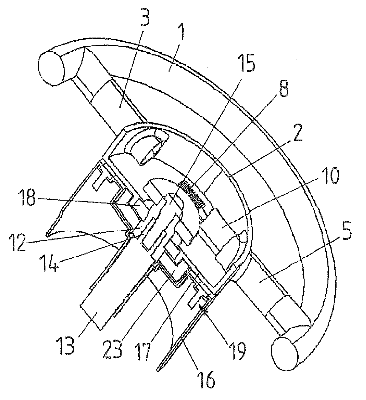
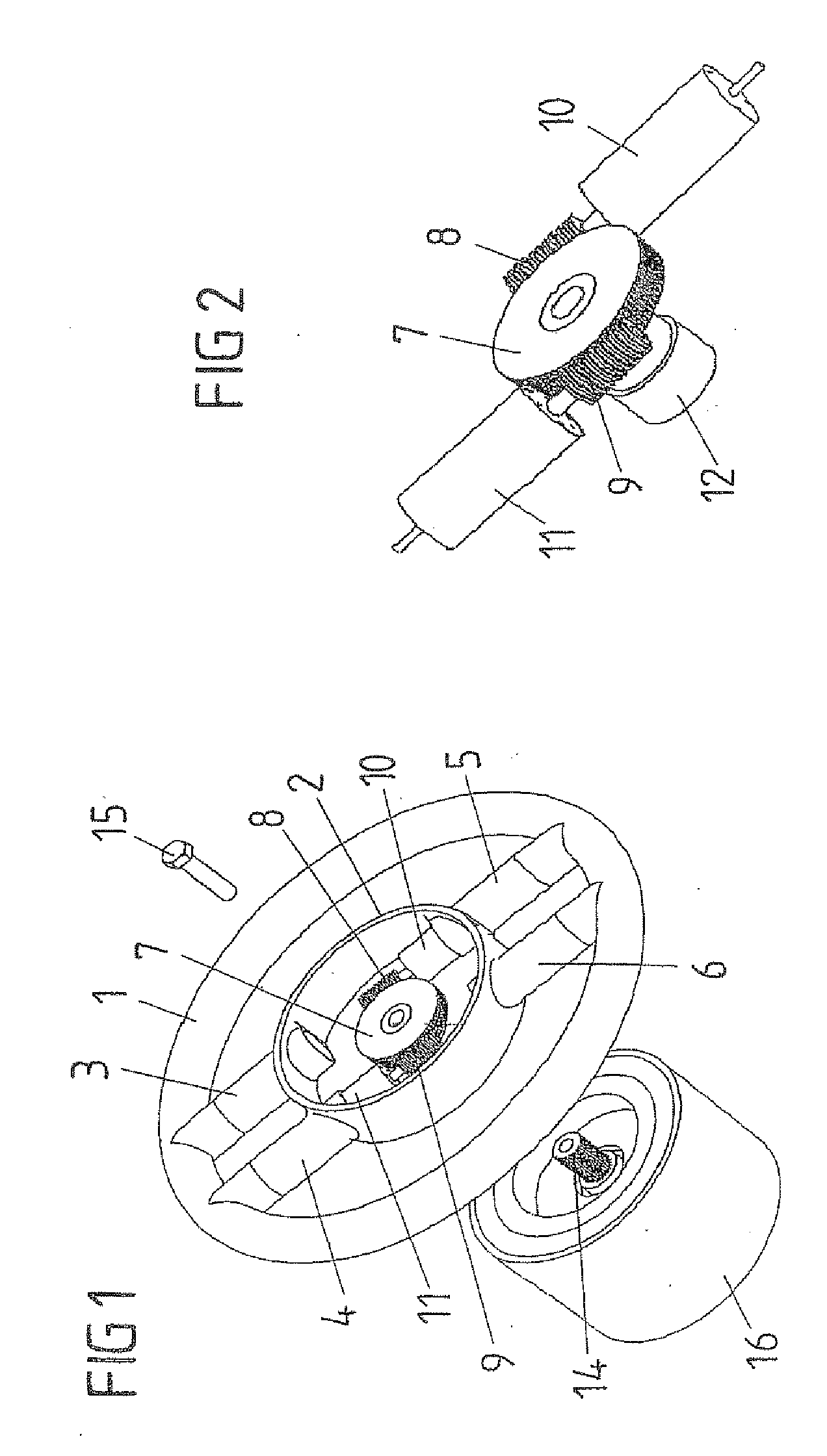
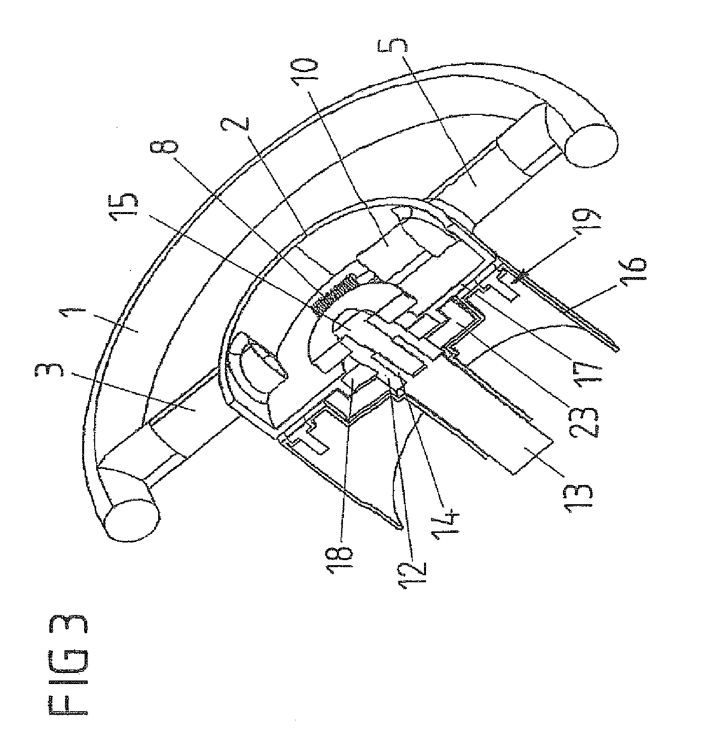
[0040]FIG. 1 shows a steering wheel which has a steering wheel rim 1 and a steering wheel hollow 2 which is shown in section, in order to make an actuator visible. The steering wheel rim 1 and the steering wheel hollow 2 are connected to one another by spokes 3, 4, 5, 6. The actuator has a large worm gear 7, two small worm gears 8, 9 and electric motors 10, 11 which are assigned to the latter. The electric motor 10 is a constituent part of the spoke 5, while the electric motor 11 is a constituent part of the spoke 4. The large worm gear 7 has a sleeve 12 (FIG. 2), by means of which the steering wheel can be fastened on a steering shaft 13 (FIG. 3). The sleeve 12 engages over a steering wheel journal 14 and the two are connected to one another by means of a screw 15.

[0041]Further details of the arrangement according to the invention can be seen from FIG. 3. The steering wheel hollow 2 has a steering wheel base 17, in which a ball bearing 18 is provided for mounting the sleeve 12. The...


PUM


Abstract

A steering device for a superposition steering system is provided using at least one actuator. The device is based on the object of producing a superposition steering system which requires no additional installation space in the steering column. The actuator for the superposition steering system is therefore arranged in the steering wheel.

Description

CROSS REFERENCE TO RELATED APPLICATIONS[0001]This is a continuation application of prior application number PCT / DE2006 / 001151, filed Jun. 29, 2006 and claims the benefit under 35 U.S.C. § 119 of prior foreign application number DE 10 2005 034 636.7, filed Jul. 20, 2005.FIELD OF THE INVENTION[0002]The invention relates to a steering device for a superposition steering system.BACKGROUND OF THE INVENTION[0003]Nowadays, motor vehicles are equipped as a rule with power steering systems. It is an object of the power steering system to reduce the steering force requirement, that is to say the torque which is to be applied by the driver for a change in driving direction. In known power steering systems, this takes place as a function of the engine speed, since the pump for the assisting hydraulic system is driven by the vehicle motor. Furthermore, it is known to drive the pumps by actuable electric motors, as a result of which speed-dependent steering force assistance is made possible. Here...

Claims


Application Information

Patent Timeline
IPC IPC(8): B62D1/04
CPCB62D5/008B62D1/10
Inventor MARKFORT, DIETER
Owner JOYSON SAFETY SYST GERMANY GMBH
Learn More