Vehicle drive system

a drive system and vehicle technology, applied in the direction of elastic bearings, bearing unit rigid support, gearing, etc., can solve the problems of increasing vibration and noise, affecting the transmission of vibration and noise, and difficulty in designing the installation layout of the drive unit, so as to minimize the occurrence of nose-dive and heavy weight

Inactive Publication Date: 2008-06-19
NISSAN MOTOR CO LTD
View PDF18 Cites 2 Cited by
  • Summary
  • Abstract
  • Description
  • Claims
  • Application Information

AI Technical Summary

Benefits of technology

[0012]With the power train set forth above, due to the presence of a layout wherein the engine and the transmission, both of which are heavy in weight, are separately disposed in the fore and aft areas of the vehicle body, a weight balance between the fore and aft areas of the vehicle body is made favorable, minimizing the occurrence of nose-dive during braking with a resultant turning ability.
[0034]Such a structure results in an increase in length of the hose 115. Thus, a large number of clamps 116 are required, thereby increasing costs.
[0039]It is an object of the present invention to provide a vehicle drive system that is able to suppress the occurrence of vibrations resulting from a drive unit system to reduce vibrations and noises and has improved driving stability, turning ability, and an expanded lockup range of a torque converter.
[0040]It is another object of the present invention to provide a vehicle drive system that is able to provide an ease of installation layout for a rear drive unit and to contribute to reduction in weight of a vehicle body through miniaturization of a rear sub frame in light weight.
[0041]It is a further object of the present invention to provide a vehicle drive system that is able to stabilize an intensity of preload of a bearing through which a differential pinion shaft is supported while providing an ease of achieving individual research and development of a transmission and a differential and combination between the transmission and differential in a variety of specifications and providing an ease of trouble shootings and replacing component parts.

Problems solved by technology

However, since the propeller shaft rotates at the engine rotation speed at all times, the propeller shaft is caused to deflect and vibrate, causing influence on vibrations and noises to be transmitted to the interior or the exterior of the vehicle compartment.
Further, since the torque converter and the transmission are integrally structured, there still remains an issue of an increase in vibrations and noises, as a result of deflections of these component parts, and the occurrence in lockup vibrations.
Additionally, the transmission, which is heavier than the differential, is mounted on an upper side of the differential with a resultant increase in height dimension of the drive unit, causing a difficulty of designing an installation layout of the drive unit.
Also, a rear sub frame for mounting the drive unit is required to have an increased thickness and cross sectional area with a resultant increase in strength and rigidity in order to have a capability of adequately bearing dynamic load of the drive unit, resulting in an increase in weight.

Method used


Image

  • Vehicle drive system
  • Vehicle drive system
  • Vehicle drive system

Examples


first embodiment

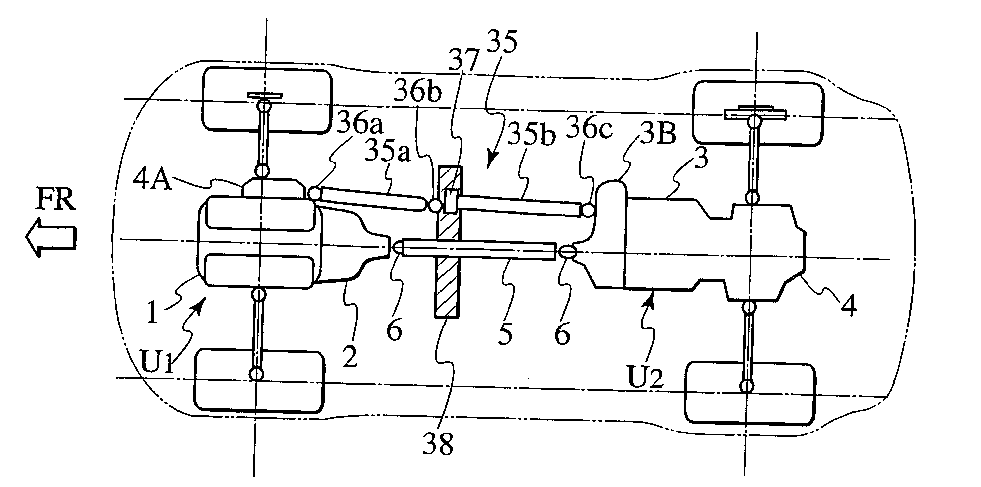
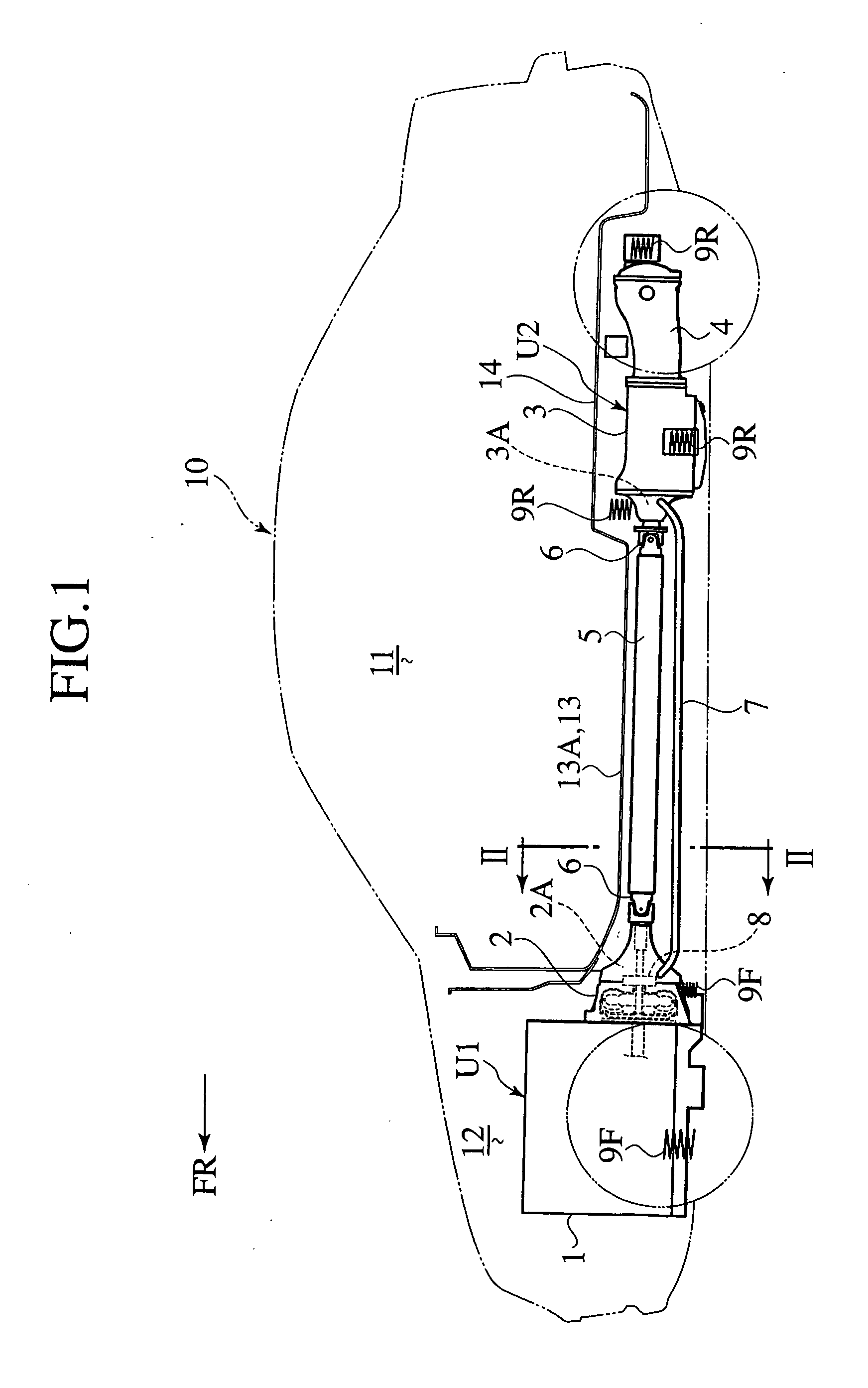
[0076]With a drive system of the embodiment, as shown in FIG. 1, a torque converter2 and a transmission 3 are separated from one another. The torque converter 2 is assembled to a rear end of an engine 1 in a unitary structure to form a front drive unit U1. The transmission 3 is integrally assembled with a front end of a differential 4 to form a rear drive unit U2.

[0077]A vehicle of this embodiment is an A / T vehicle of a front engine with a rear drive type. The vehicle is shown as including a vehicle body 10 that has a vehicle compartment 11 and a front compartment 12, located in front of the vehicle compartment 11, in which the front drive unit U1 is installed. The rear drive unit U2 is mounted in an area beneath a rear floor 14. Thus, the front and rear drive units U1, U2 are separately located in front and rear areas of the vehicle body 10.

[0078]The front drive unit U1 is resiliently supported on sub frames or vehicle body front frame members at three mount positions, involving ce...

second embodiment

[0097]The second embodiment differs from the first embodiment in that the rear drive unit U2 is resiliently supported in a way to straddle a rear seat cross member 15 and a rear sub frame 16 as shown in FIG. 4.

[0098]Now, description is made focusing on such a different point.

[0099]The rear sub frame 16 supports the rear drive unit U2 at a rear end thereof. The rear sub frame 16 is formed with fore and aft frames 16A, 16B and a pair of side frames 16C in planar parallel crosses. The rear sub frame 16 has both fore and rear distal ends formed with rest portions 16D through which the rear sub frame 16 is coupled to a floor frame member joined to a lower surface of the rear floor 14. The differential 4 has a rear end that is resiliently supported on the rear frame 16B by means of a vibration-proof bush 17 that is located in and extends through a central area, along a vehicle widthwise direction, of the aft frame 16B in a fore and aft direction.

[0100]In the meanwhile, the transmission 3 ...

third embodiment

[0117]FIG. 10 shows a vehicle drive system of a third embodiment according to the present invention. Hereinafter, the same component parts as those of the second embodiment bear like reference numerals to omit redundant description.

[0118]With the structure of the third embodiment, the mount member 18 is a stay 18B having a vibration-proof mount member 22A by which the front portion of the transmission 3 is supported.

[0119]The stay 18B is made of lightweight metal, such as aluminum alloy, formed by die-casting. The stay 18B is formed in a structure that straddles the lower opening of the tunnel portion 15 of the rear seat cross member 15. Thus, the stay 18B has both lateral ends to be fixedly fastened to the left and right lower surfaces of the bottom walls of the rear seat cross member 15 on both sides of the lower opening.

[0120]Formed on a substantially central area of the stay 18B is a ridge portion 18B′, on which a vibration-proof mount member 22A is located.

[0121]Formed on a low...


PUM


Abstract

A vehicle drive system including: a front drive unit in a front part of a vehicle, which has an engine and a torque converter integrally assembled to one another; a rear drive unit in a rear part of the vehicle, which has a transmission and a differential integrally assembled to one another; and a drive shaft connecting the torque converter of the front drive unit and the transmission of the rear drive unit. The drive shaft is configured to be elastically twistable for damping vibration transmission between the front and rear drive units.

Description

BACKGROUND OF THE INVENTION[0001]1. Field of Invention[0002]The present invention relates to a vehicle drive system including an engine and a power train, particularly to a vehicle drive system for an automatic transmission (A / T) vehicle.[0003]2. Description of Related Art[0004]Generally, a drive unit U of an A / T vehicle of a front engine and rear drive type is structured with an engine A, a torque converter B and a transmission C, which are arranged from a front side in this order and integrally assembled as shown in FIG. 26. The drive unit U is installed in a front compartment of a vehicle body separately defined in front of a vehicle compartment thereof. Meanwhile, a differential is mounted on the vehicle body in a space beneath a rear floor. An output shaft of the transmission is connected to an input shaft of the differential through a steel propeller shaft for transmitting power of the engine.[0005]Since the engine A and the transmission C are integrally assembled to one anoth...

Claims


Application Information

Patent Timeline
Patent Type & Authority Applications(United States)
IPC IPC(8): B60K17/24B60K17/04B60K17/22B60K17/344B62D21/11B62D25/20F16C27/06F16H48/42F16H57/02F16H57/022F16H57/027F16H57/037F16H57/04
CPCB60K17/04F16C2361/61B60K17/22B60K17/34B60K17/344B62D21/11B62D25/2027F16C27/063F16H57/02F16H57/027F16H57/037F16H57/0445F16H2048/423F16H2057/02013F16H2057/02043F16H2057/0221F16C2326/06B60K17/06
Inventor MIZUNO, KAZUTOSHITAKAHASHI, KOUJINOMURA, HIROYUKIYAMATAKA, TATSUROAKAMINE, SEIJINAKATSUKASA, HARUAKI
Owner NISSAN MOTOR CO LTD
Why Eureka
Try Eureka