Determining Properties of Earth Formations Using the Electromagnetic Coupling Tensor

a technology of electromagnetic coupling and earth formation, applied in the field of welllogging, can solve the problems of electronic drift affecting the coupling between t and r coils, limiting the measurement to simple ratios of electromagnetic coupling tensor elements, and the efficiency of coils

Active Publication Date: 2008-06-19
SCHLUMBERGER TECH CORP
View PDF7 Cites 64 Cited by
  • Summary
  • Abstract
  • Description
  • Claims
  • Application Information

AI Technical Summary

Problems solved by technology

An inherent difficulty in using these tools is that the coil efficiency, and electronic drift affects the coupling between T and R coil

Method used


Image

  • Determining Properties of Earth Formations Using the Electromagnetic Coupling Tensor
  • Determining Properties of Earth Formations Using the Electromagnetic Coupling Tensor
  • Determining Properties of Earth Formations Using the Electromagnetic Coupling Tensor

Examples


Embodiment Construction

[0017]Refer now to the drawings wherein depicted elements are not necessarily shown to scale and wherein like or similar elements are designated by the same reference numeral through the several views.

[0018]As used herein, the terms “up” and “down”; “upper” and “lower”; and other like terms indicating relative positions to a given point or element are utilized to more clearly describe some elements of the embodiments of the invention. Commonly, these terms relate to a reference point as the surface from which drilling operations are initiated as being the top point and the total depth of the well being the lowest point. In addition, the terms “coil” and “antenna” may be used interchangeably herein in both the description and the claims.

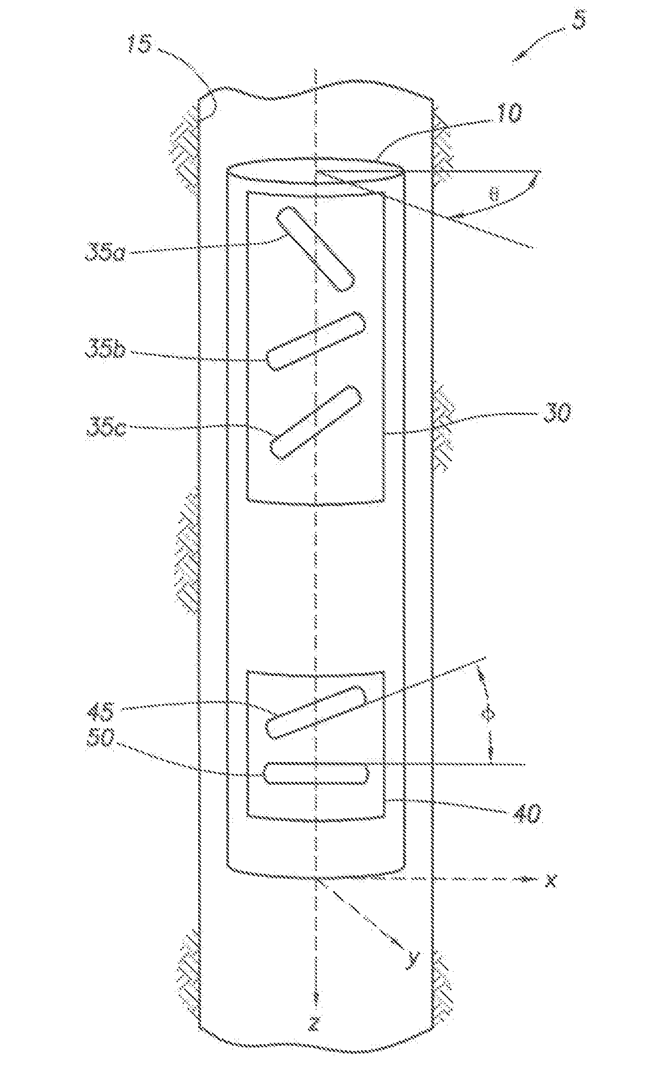
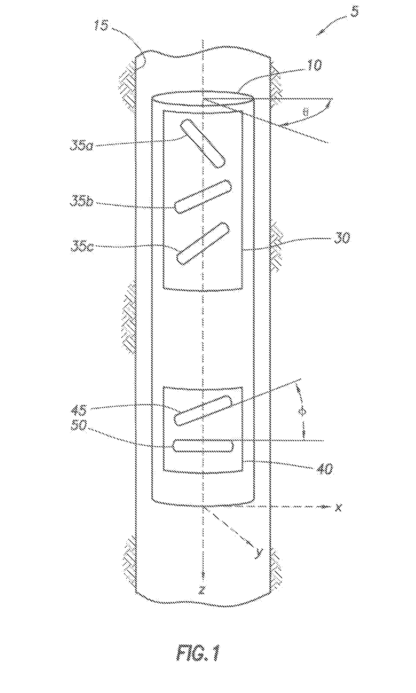
[0019]FIG. 1 is a schematic drawing of a logging system of the present invention, generally denoted by 5. Tool 10 may be lowered into borehole 15 that has been created in earth formation 20. Tool 10 may be any tool suitable for measuring the resistivi...


PUM


Abstract

A system and method to determine earth formation properties by positioning a logging tool within a wellbore in the earth formation, the logging tool having a tool rotation axis and a first, a second, and a third tilted transmitter coil, and a tilted receiver coil; rotating the logging tool about the tool rotation axis; energizing each transmitter coil; measuring a coupling signal between each transmitter coil and the receiver coil for a plurality of angles of rotation; determining a coupling tensor; and determining the earth formation properties using the coupling tensor.

Description

FIELD OF THE INVENTION[0001]The present invention relates to well logging and, more particularly, to determining earth formation properties using the entire electromagnetic coupling tensor of an earth formation in a gain-corrected manner.BACKGROUND[0002]In petroleum exploration and development, formation evaluation is used to determine whether a potential oil or gas field is commercially viable. One factor to determining the commercial viability of a potential field is the resistivity of the earth formation. The resistance to electric current of the total formation-rock and fluids-around the borehole is the sum of the volumetric proportions of mineral grains and conductive water-filled pore space. If the pores are partially filled with gas or oil, which are resistant to the passage of electrical current, the bulk formation resistance is higher than for water-filled pores.[0003]Conventional induction logging tools use multiple coils to measure the conductivity (i.e., the inverse of r...

Claims


Application Information

Patent Timeline
IPC IPC(8): G01V3/18G01V3/10
CPCG01V3/28G01V3/38
Inventor LEGENDRE, EMMANUELSEYDOUX, JEANTAHERIAN, REZA
Owner SCHLUMBERGER TECH CORP
Why Eureka
Try Eureka