Antenna-integrated module

a technology of integrated modules and antennas, applied in the direction of collapsible antennas, quick-releasable antenna elements, resonant antennas, etc., can solve the problems of difficult to arbitrarily alter the major part of the high frequency circuit of the antenna-integrated module, difficult to insert the soldering iron or the like into the space covered with the covering antenna element from the side, etc., to achieve the effect of reducing the size of the entire module, reducing manufacturing

Inactive Publication Date: 2008-06-19
ALPS ALPINE CO LTD
View PDF5 Cites 10 Cited by
  • Summary
  • Abstract
  • Description
  • Claims
  • Application Information

AI Technical Summary

Benefits of technology

[0011]The antenna-integrated module having the above-described configuration can serve as a shield chase for electrically shielding the circuit elements of the high frequency circuit and can also serve as an antenna element of an inverted F-type metal plate antenna by using the top plate as a radiation conductor. Accordingly, it is possible to decrease the size of the entire module and decrease manufacturing cost, compared with a configuration in which a special antenna element and a shield case are disposed in line in plan view. Since the openings are formed at a plurality of positions of the top plate and air can be circulated through the openings, heat can be easily delivered to the region of the circuit board covered with the covering antenna element in the reflow process. Accordingly, the reflow soldering process of the circuit elements mounted on the circuit board and the reflow soldering process of the covering antenna element can be performed together. In addition, since the openings are formed in the slit shape or the small hole shape, it is difficult to inserting a soldering iron or the like into the openings. Since the side plates extend from the periphery of the top plate to the circuit board, it is also difficult to insert the soldering iron or the like into the space covered with the covering antenna element from the side. Therefore, it is difficult to arbitrarily alter the major part of the high frequency circuit of the antenna-integrated module.
[0012]In the antenna-integrated module having the above-described configuration, in the side plates, the slit-like or small hole-like openings may be formed at a plurality of positions spaced from the periphery of the side plates. In this case, preferably, heat can be more easily delivered to the region of the circuit board covered with the covering antenna element in the reflow process.
[0013]In the antenna-integrated module having the above-described configuration, the top plate may have a rectangular shape, and the short-circuited leg pieces may extend from two positions of one end of the top plate in a longitudinal direction of the top plate and the support leg pieces extend from two positions of the other end of the top plate in the longitudinal direction. In this case, since the shape of the covering antenna element can be simplified, the manufacturing is preferably facilitated. In addition, a third support leg piece having the same shape as the power feeding leg piece may be formed at a position point-symmetrical to the power feeding leg piece, so that the covering antenna element has the symmetrical shape of which the outer appearance is not different even when both ends of the covering antenna element in the longitudinal direction is reversed. In a manufacturing process of mounting the covering antenna element on the circuit board, it is not necessary to check the direction of the antenna element, thereby improving working efficiency.
[0014]In the antenna-integrated module having the above-described configuration, the circuit board may be configured to be inserted into or extracted from a connector and the connector has guide pieces which interpos...

Problems solved by technology

In addition, since the openings are formed in the slit shape or the small hole shape, it is difficult to inserting a soldering iron or the like into the openings.
Since the side plates extend from the periphery of the top plate to the circuit board, it...

Method used


Image

  • Antenna-integrated module
  • Antenna-integrated module
  • Antenna-integrated module

Examples


first embodiment

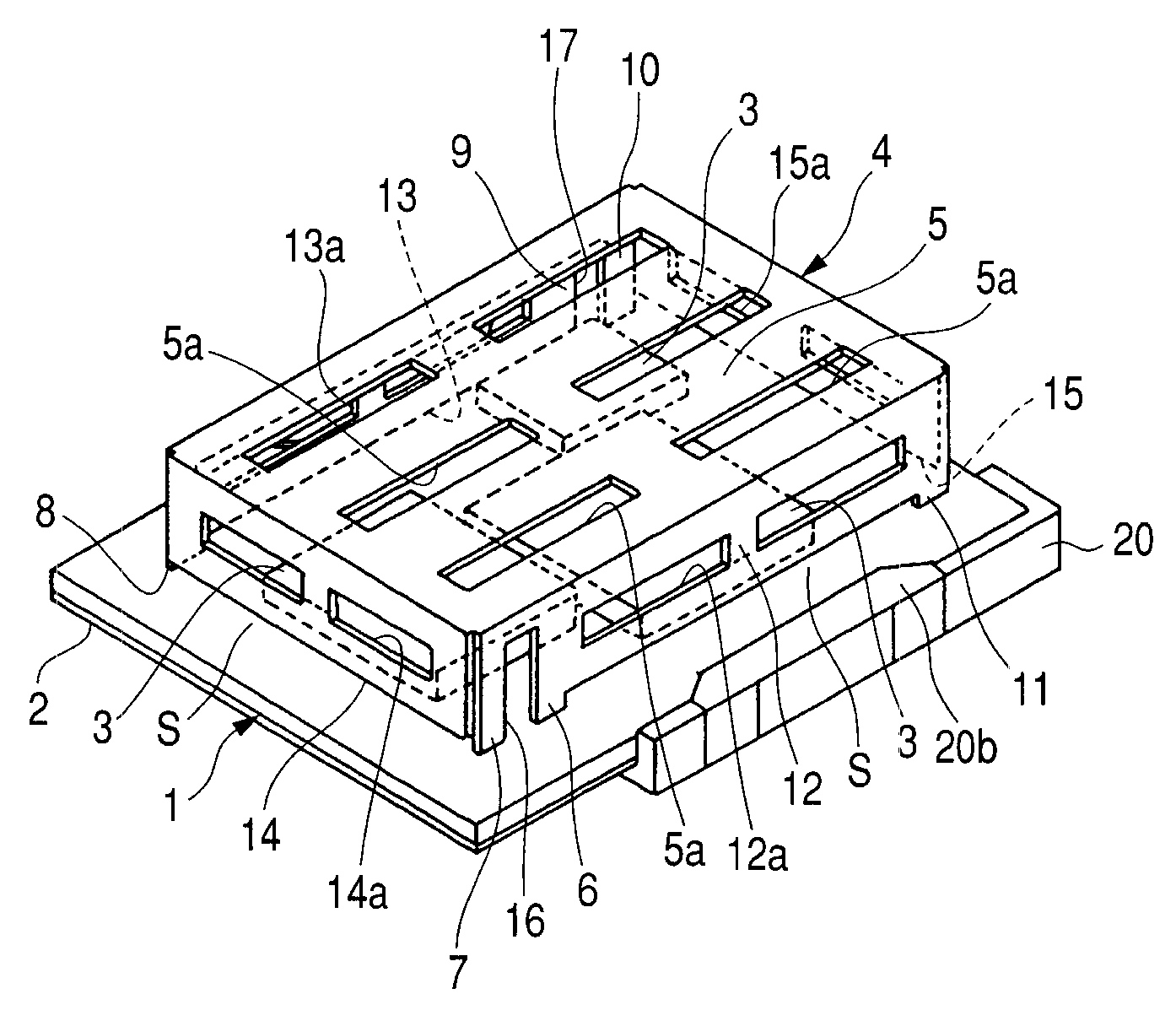
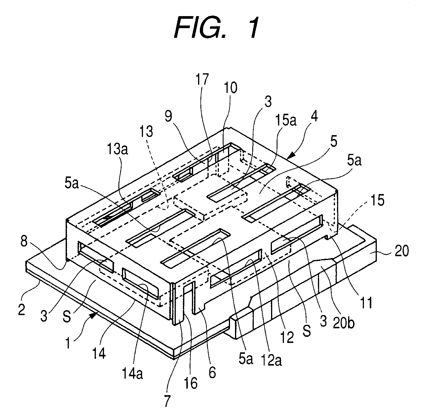
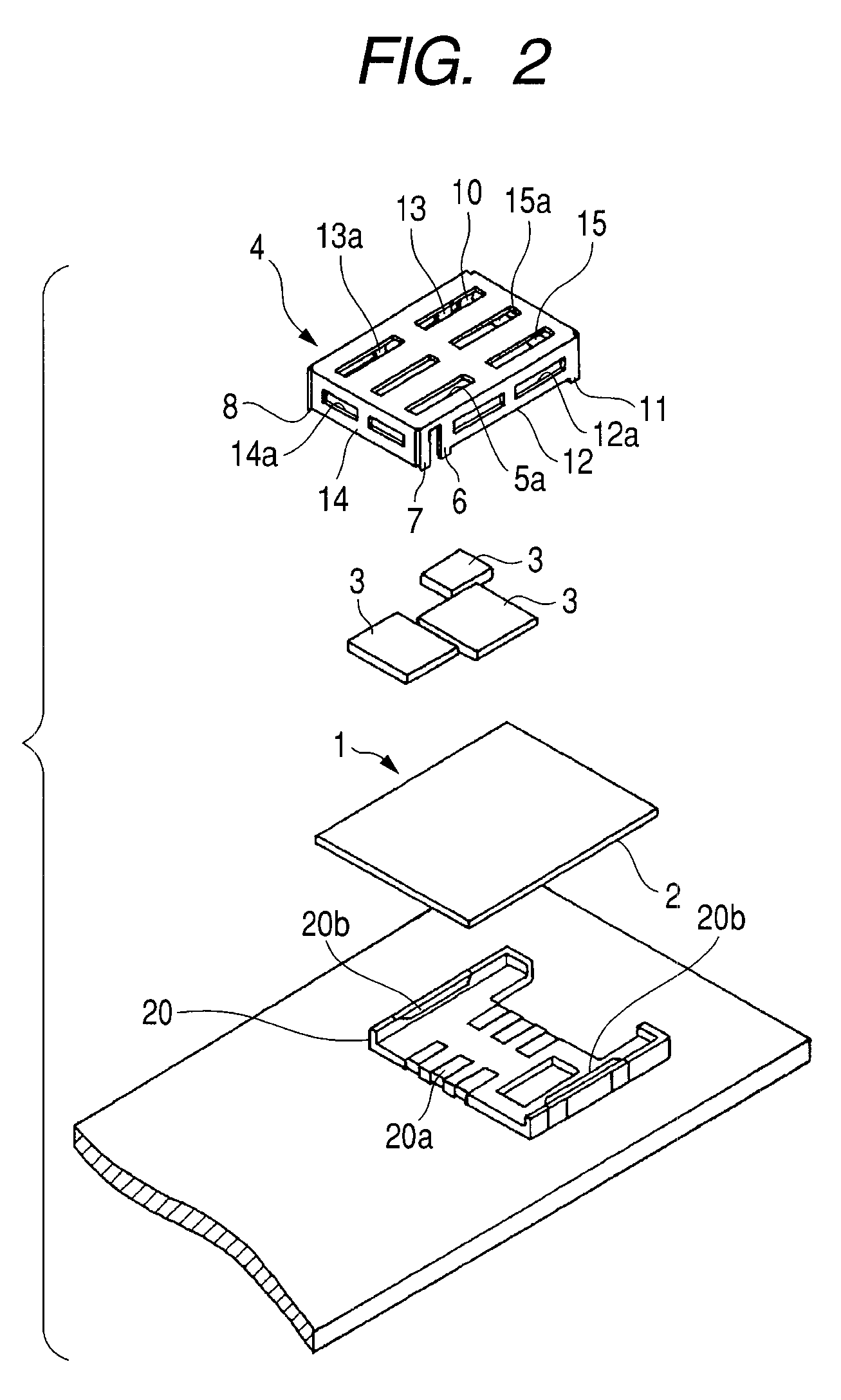
[0021]Embodiments of the invention will be described with reference to the drawings. FIG. 1 is a perspective view illustrating an antenna-integrated module according to the invention. FIG. 2 is an exploded perspective view illustrating a module and a connector shown in FIG. 1.

[0022]The antenna-integrated module shown in FIGS. 1 and 2 includes a rectangular circuit board 1 of which the upper surface is provided with a wiring pattern of a high frequency circuit and of which the entire lower surface is provided with a ground conductive layer 2, circuit elements 3 such as a chip element or an IC which are mounted on the upper surface of the circuit board 1 so as to be connected to the wiring pattern, and a sheet-metal covering antenna element 4 which is mounted on the circuit board 1 so as to cover the circuit elements 3. The circuit board 1 is electrically and mechanically connected to a main board 30 with a connector 20 interposed therebetween. The connector 20 includes a plurality of...

second embodiment

[0031]FIG. 3 is a perspective view illustrating an antenna-integrated module according to the invention. FIG. 4 is a sectional view illustrating the antenna-integrated module taken along the line IV-IV line shown in FIG. 3. In addition, the same reference numerals are given to the same elements corresponding to those in FIGS. 1 and 2.

[0032]The second embodiment of the invention is different from the first embodiment described above in that a circuit board 1 of a top plate 5 has a squire with the substantially same width and a power feeding leg piece 6, short-circuited leg pieces 7 and 8, support leg pieces 9 to 11 extending from the top plate 5 are formed at different positions. In addition, other configuration and operational effect are basically the same. That is, a side plate 14 along one short side of the top plate 5 is a bent piece of which one end portion in the transverse direction thereof is adjoined with the power feeding leg piece 6, a center portion is adjoined with the s...


PUM


Abstract

The present invention provides an antenna-integrated module capable of decreasing the size thereof, facilitating prevention of arbitrary alternation to the circuit, effectively performing a reflow process, and being manufactured at low cost. Circuit elements 3 are mounted on a circuit board 1 with a wiring pattern and a ground conductive layer 2 and a sheet-metal covering antenna element 4 mounted on the circuit board 1 covers the circuit elements 3. The covering antenna element 4 includes a rectangular top plate 5 with openings 5a, a power feeding leg piece 6 connected to a feeding line of the wiring pattern, short-circuited leg pieces 7 and 8 connected to the ground conductive layer 2, support leg pieces 9 to 11 electrically opened, side plates 12 to 15 with openings 12a to 15a and the pieces 6 to 11 are soldered on the circuit board 1.

Description

BACKGROUND OF THE INVENTION[0001]1. Field of the Invention[0002]The present invention relates to an antenna-integrated module suitable for a small-sized transceiver used for communication or broadcasting.[0003]2. Description of the Related Art[0004]In recent years, as wireless communication techniques have been developed, various electronic apparatuses or wireless cards in which small-sized transceiver units are mounted have been proposed. This type of each transceiver unit is an antenna-integrated high frequency module in which an antenna element is mounted on a circuit board with a high frequency circuit. In the known antenna-integrated module, a sheet-metal shield case covers a predetermined region of the circuit board on which the main elements of the high frequency circuit are mounted. An antenna element such as a chip antenna or a pattern antenna is mounted on other regions of the circuit board (for example, see JP-A-2002-232221 (pages 4 to 6 and FIG. 1)).[0005]However, in a s...

Claims


Application Information

Patent Timeline
IPC IPC(8): H01Q1/38
CPCH01Q1/088H01Q1/243H01Q9/0421H01Q1/52H01Q1/44
Inventor WATANABE, HIROKAZUSUZUKI, TOMOTAKAMURATA, ATSUSHIWATANABE, YOSHIKIYO
Owner ALPS ALPINE CO LTD
Why Eureka
Try Eureka