Optical calibration system and method

a technology of optical power and calibration system, applied in the field of optical system calibration system and method, can solve the problems accuracy of mechanical alignment, and accuracy of mechanical alignment accuracy, and achieve the effect of improving mechanical alignment repeatability and accuracy

Active Publication Date: 2008-06-19
BAUSCH & LOMB INC
View PDF17 Cites 15 Cited by
  • Summary
  • Abstract
  • Description
  • Claims
  • Application Information

AI Technical Summary

Problems solved by technology

Alignment has always been a serious issue in creating eye models from image data.
Misalignment errors directly result in errors in both estimates of optical power and details about the reconstructed ocular surfaces.
There are several drawbacks associated with the aforementioned calibration technique and apparatus.
The precise placement of the test plates presents challenges in regard to mechanical alignment repeatability and mechanical alignment accuracy.
Traditional alignment plates / fixtures can unknowingly be bent or otherwise deformed thus affecting alignment accuracy.
The need for multiple physical alignment measurements and sets of images increases the opportunity for error.

Method used


Image

  • Optical calibration system and method
  • Optical calibration system and method
  • Optical calibration system and method

Examples


Embodiment Construction

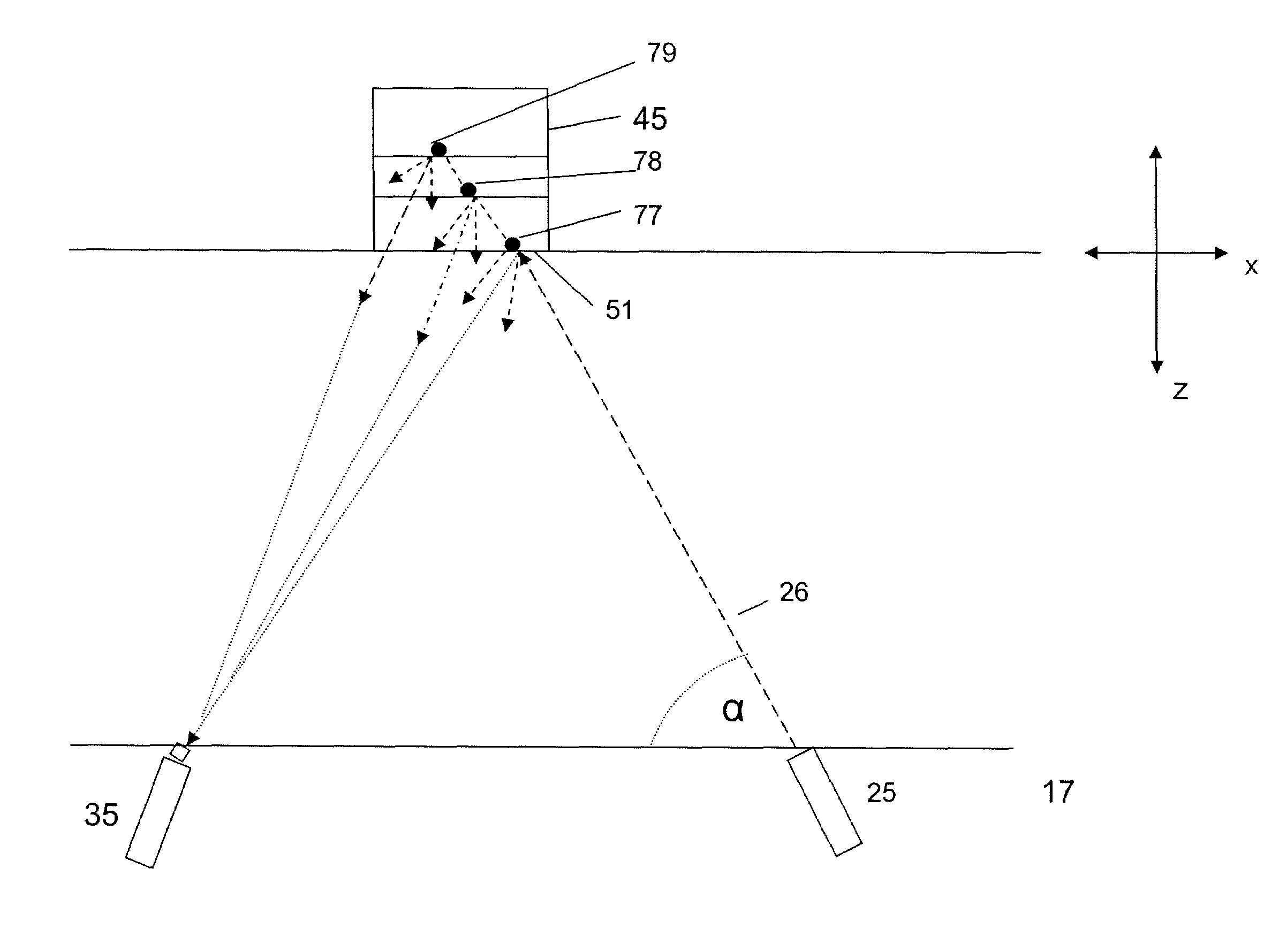
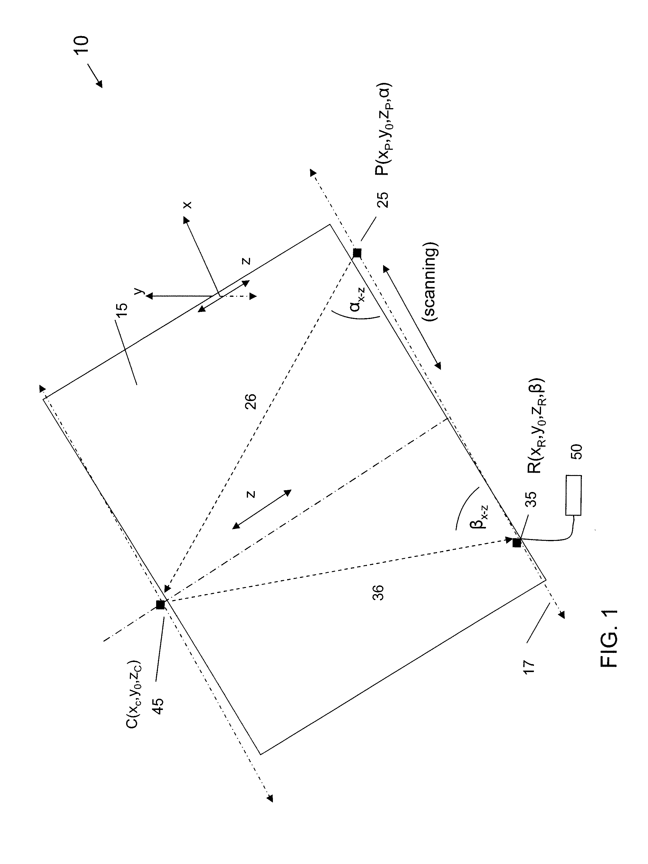
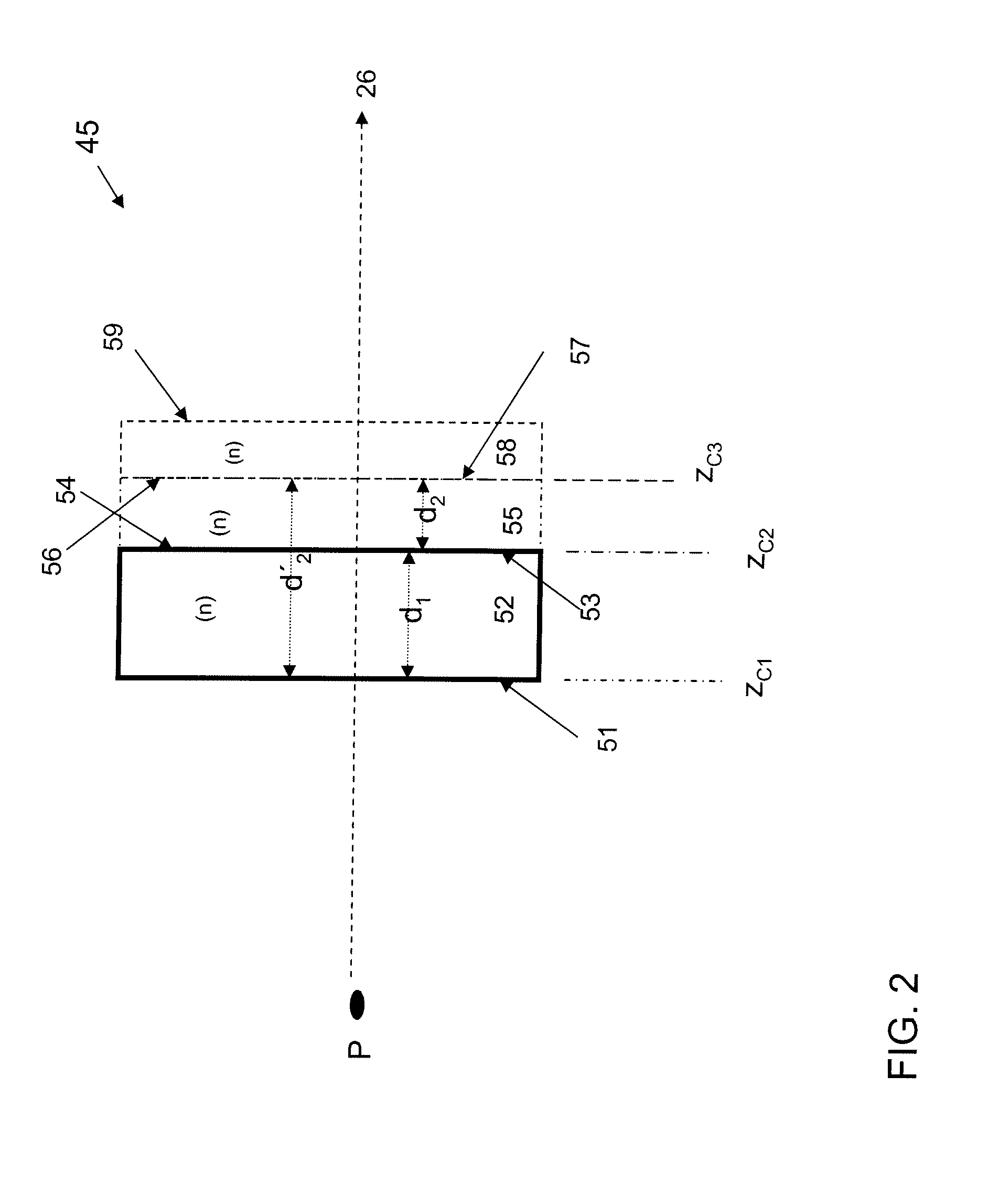
[0025]An embodiment of the invention is directed to a slit plane image calibration system 10 as illustrated in FIG. 1. The calibration system is particularly suited to calibrating slit beam-based ophthalmic instruments such as anterior chamber analyzers from Bausch & Lomb Incorporated and Nidek Co., LTD, for example, or slit beam pachymeters (see, e.g., Snook U.S. Pat. No. 6,193,371). In these types of instruments, a slit beam is scanned across a subject's eye and a series of slit beam images is taken to obtain cross sectional viewing of the subject's cornea and to reconstruct corneal profiles, including an anterior surface profile, a posterior surface profile, and a corneal thickness profile. Thus embodiments according to the invention can be used to measure the slit beam profile and to determine the optical path of the slit beam at various scanning positions of the slit beam. The slit beam profile includes the slit beam width across the slit plane and the slit beam width variation...


PUM

PropertyMeasurementUnit
angleaaaaaaaaaa
angleaaaaaaaaaa
angleaaaaaaaaaa

Abstract

An optical system calibration system and method particularly suited for calibrating the optical slit planes in an ophthalmic diagnostic instrument. The system includes an illumination source projector, an illumination image receiver, and a calibration component all having known relative positions, orientations and physical and optical characteristics. The calibration component includes at least two separated, diffusely reflecting surfaces. Images of an exemplary slit illumination pattern projected onto the calibration component and formed on the diffusely reflecting surfaces are detected by the image receiver such as a video camera. Based upon camera image coordinates and triangulation parameters of the projector, the receiver, and the calibration component, the slit image positions on the image detector plane can be calibrated to the axially displaced, diffusely reflecting calibration component surface positions.

Description

CROSS REFERENCE TO RELATED APPLICATIONS[0001]N / A.FEDERALLY SPONSORED RESEARCH[0002]N / A.BACKGROUND OF THE INVENTION[0003]1. Field of the Invention[0004]Embodiments of the invention generally relate to an optical system calibration system and method. More particularly, embodiments of the invention are directed to a system and method for calibrating an ophthalmic diagnostic instrument. Most particularly, an optical slit plane calibration apparatus and method are disclosed.[0005]2. Description of Related Art[0006]Eye models provide a valuable tool for assessing the optical, physical and biophysical characteristics of human eyes and those of other species. In order to construct accurate eye models, the shapes and locations of the various ocular surfaces as well as their functions and effects need to be known with a high degree of precision. Alignment has always been a serious issue in creating eye models from image data. Misalignment errors directly result in errors in both estimates of ...

Claims


Application Information

Patent Timeline
Patent Type & Authority Applications(United States)
IPC IPC(8): G01N21/47
CPCA61B3/1005A61B3/0025
Inventor ALLRED, LLOYD G.LAI, MING
Owner BAUSCH & LOMB INC
Why Eureka
Try Eureka