

Sleeve
- Summary
- Abstract
- Description
- Claims
- Application Information
AI Technical Summary
Benefits of technology
Problems solved by technology
Method used
Image

Examples
first embodiment
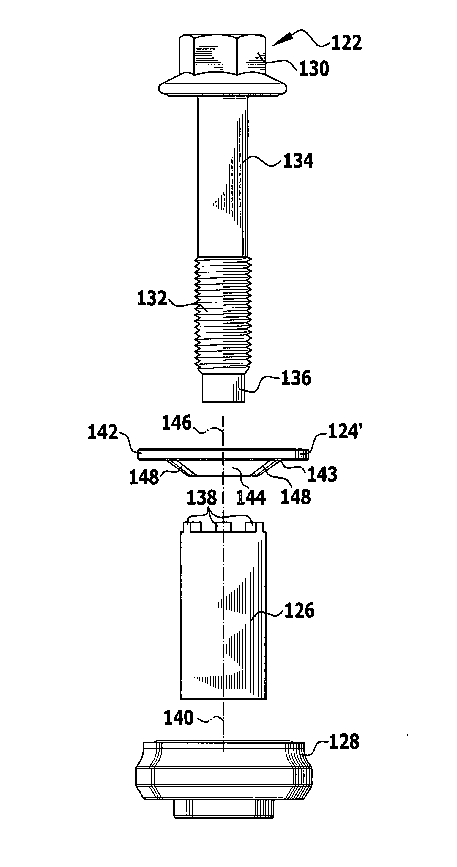
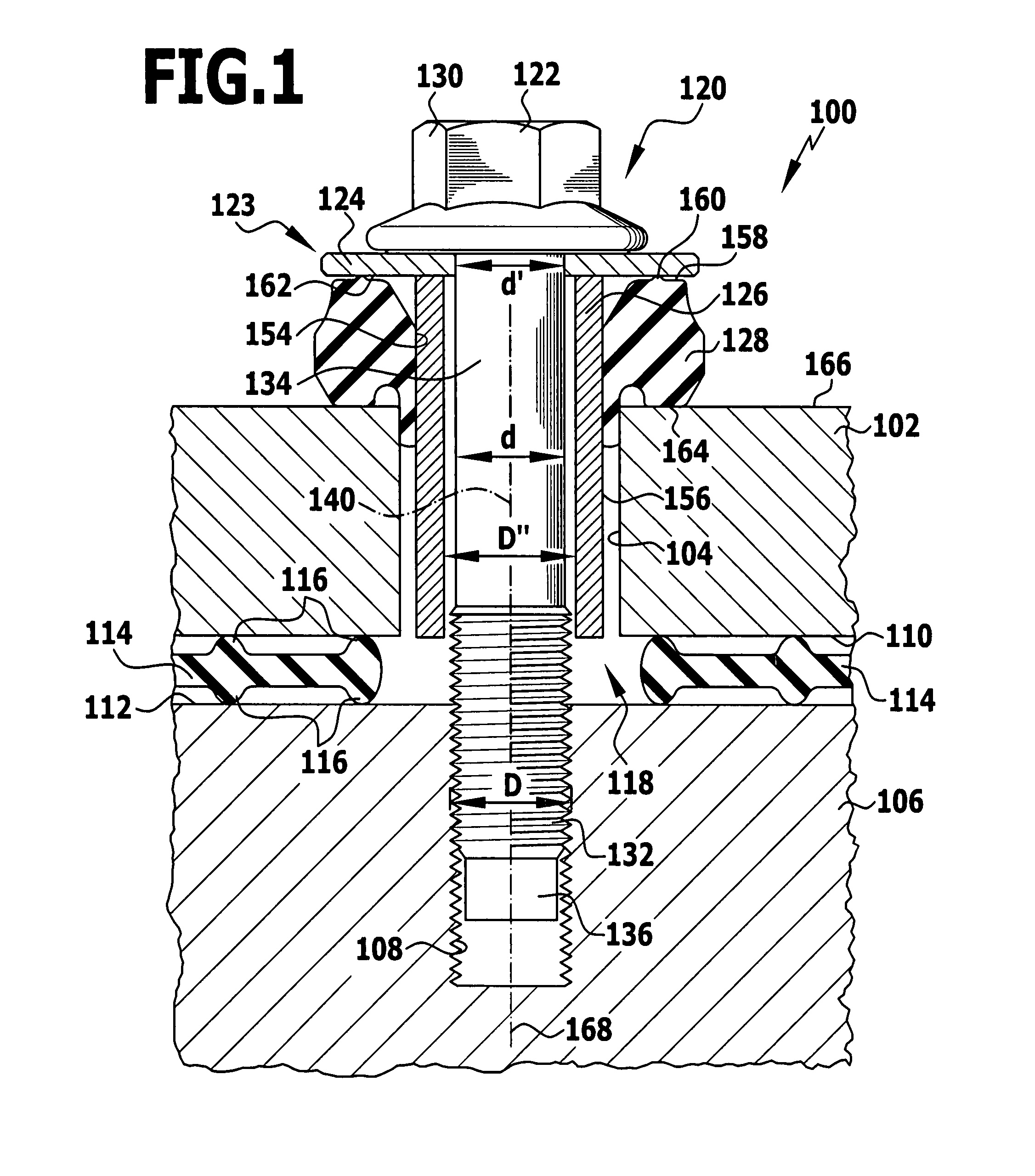
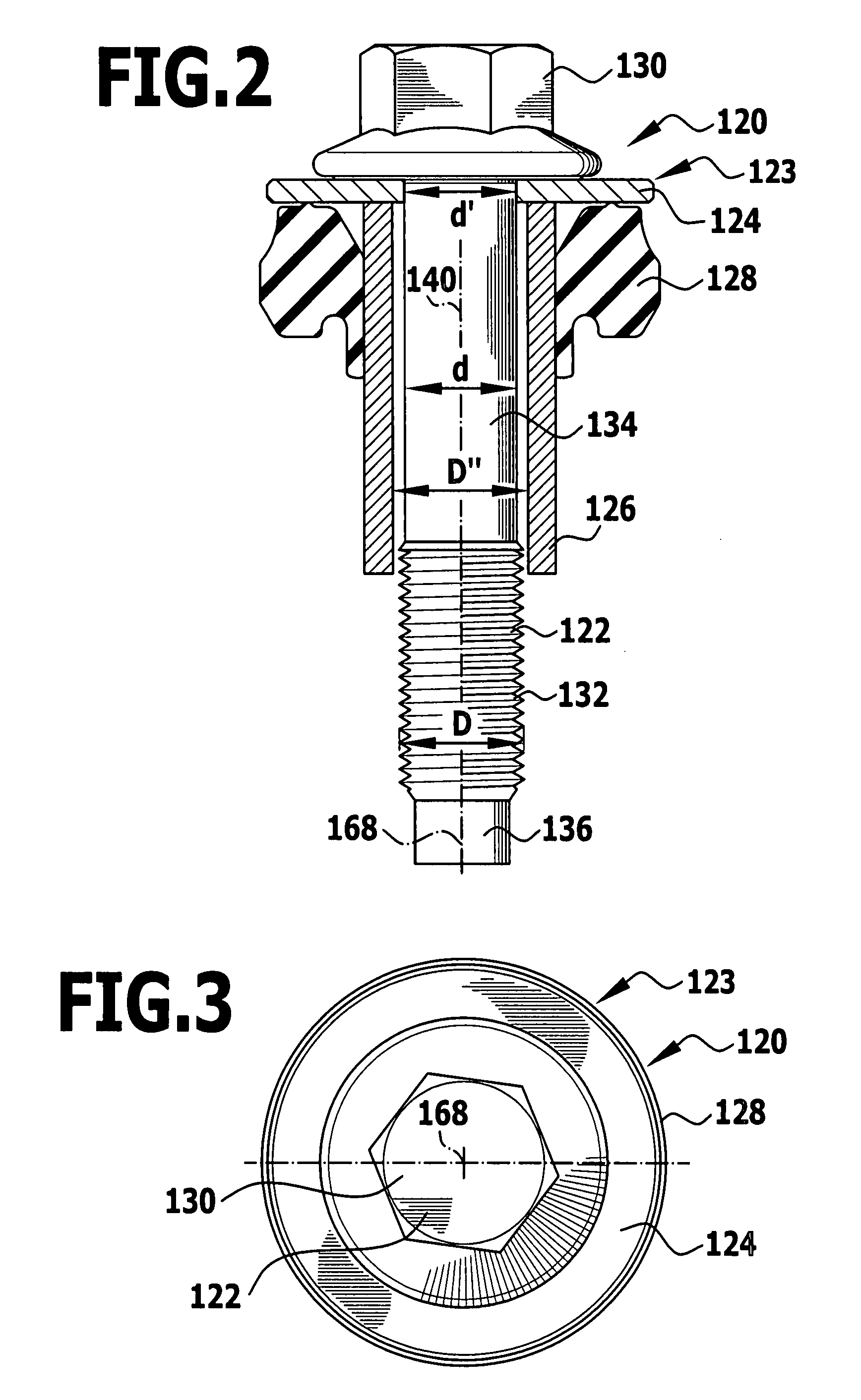
[0073]This effect is achieved in that, prior to the process of pressing the flange pre-form 124′ against the sleeve base body 126, the diameter D′ of the flange pre-form 124′ is selected to be greater than was the case in the first embodiment and in particular, it is selected to be greater than the internal diameter D″ of the sleeve base body 126, namely just so large that, after the webs 144 have been bent up into the plane of the flat ring-like region 142 of the flange pre-form 124′ during the process of pressing the sleeve base body 126 against the flange pre-form 124′, the passage opening 150 in the flange 124 has the desired diameter d′ which is of substantially the same size as the internal diameter D″ of the hollow cylindrical sleeve base body 126.
second embodiment
[0074]In the installed state of an assembly 100 such as is illustrated in FIG. 8, the sleeve base body 126 extends downwardly to the upper surface 112 of the second component 106 so that the sleeve 123 serves as a spacer between the screw member head 130 on the one hand and the second component 106 on the other.
[0075]The flange 124 of the sleeve 123 serves as a washer for the screw member 122.
[0076]In all other respects the second embodiment of a component group 100 illustrated in FIG. 8 agrees in regard to the construction, function, material and method of production as the first embodiment illustrated in FIGS. 1 to 7, so that to this extent, reference is made to the description thereof hereinabove.
PUM
 Abstract
Description
Claims
Application Information