Forced air supply combustion apparatus

Inactive Publication Date: 2008-06-19
RINNAI CORP
View PDF1 Cites 6 Cited by
  • Summary
  • Abstract
  • Description
  • Claims
  • Application Information

AI Technical Summary

Benefits of technology

[0006]The present invention has been devised in view of the circumstances and it is an object of the present invention to provide a forced air supply combustion apparatus that can uniformalize the pressure distribution in the primary air chamber and supply the primary air to all the burners equally.
[0010]Therefore, in the present invention, it is desirable that the portion of the partition plate opposed to the air supply port is formed in a concave shape recessed upward. Consequently, the air from the combustion fan, which flows in from the air supply port, is once collected in the concave shape portion of the partition plate opposed to the air supply port, a static pressure area having a uniform pressure distribution is generated, and the air is distributed from the static pressure area to the plurality of areas of the air supply chamber sectioned by the plurality of projected rims. Even if the position and angle of connection of the combustion fan to the air supply port fluctuate, since the air from the combustion fan is collected in the concave shape portion of the partition plate, the fluctuation in the position and the angle of connection of the combustion fan is absorbed. Therefore, it is possible to effectively prevent a fluctuation from occurring in the quantity of distribution of the air to the plurality of areas of the air supply chamber because of the fluctuation in the position and the angle of connection of the combustion fan.
[0011]In the present invention, it is desirable that the height of a downward projection of the respective projected rims decreases toward the respective upstream side section points. Consequently, the plurality of areas of the air supply chamber sectioned by the plurality of projected rims communicate with one another in a wide area in an upstream portion close to the air supply port. Therefore, a pressure in the upstream portion of the plurality of areas is equalized by the mutual communication. It is possible to prevent a fluctuation from occurring in the quantity of distribution of the air to the plurality of areas of the air supply chamber because of the fluctuation in the position and the angle of connection of the combustion fan to the air supply port.
[0013]In the present invention, it is desirable that a portion closer to the respective downstream side section points of the respective projected rims connecting the respective upstream side section points and the respective downstream side section points, which are offset in the horizontal direction with respect to the respective upstream side section points, extends in a front to back direction over a predetermined length. Consequently, a rectifying flow for directing an air flow to the front is obtained. It is possible to prevent the air having a motion component in the horizontal direction from flowing into the primary air chamber.

Problems solved by technology

Therefore, when the air supply port is opened in the position biased to one side in the horizontal direction, a pressure distribution in the primary air chamber becomes nonuniform and a supply quantity of the primary air to a part of the burners becomes excessively larger or excessively small.

Method used


Image

  • Forced air supply combustion apparatus
  • Forced air supply combustion apparatus
  • Forced air supply combustion apparatus

Examples


Embodiment Construction

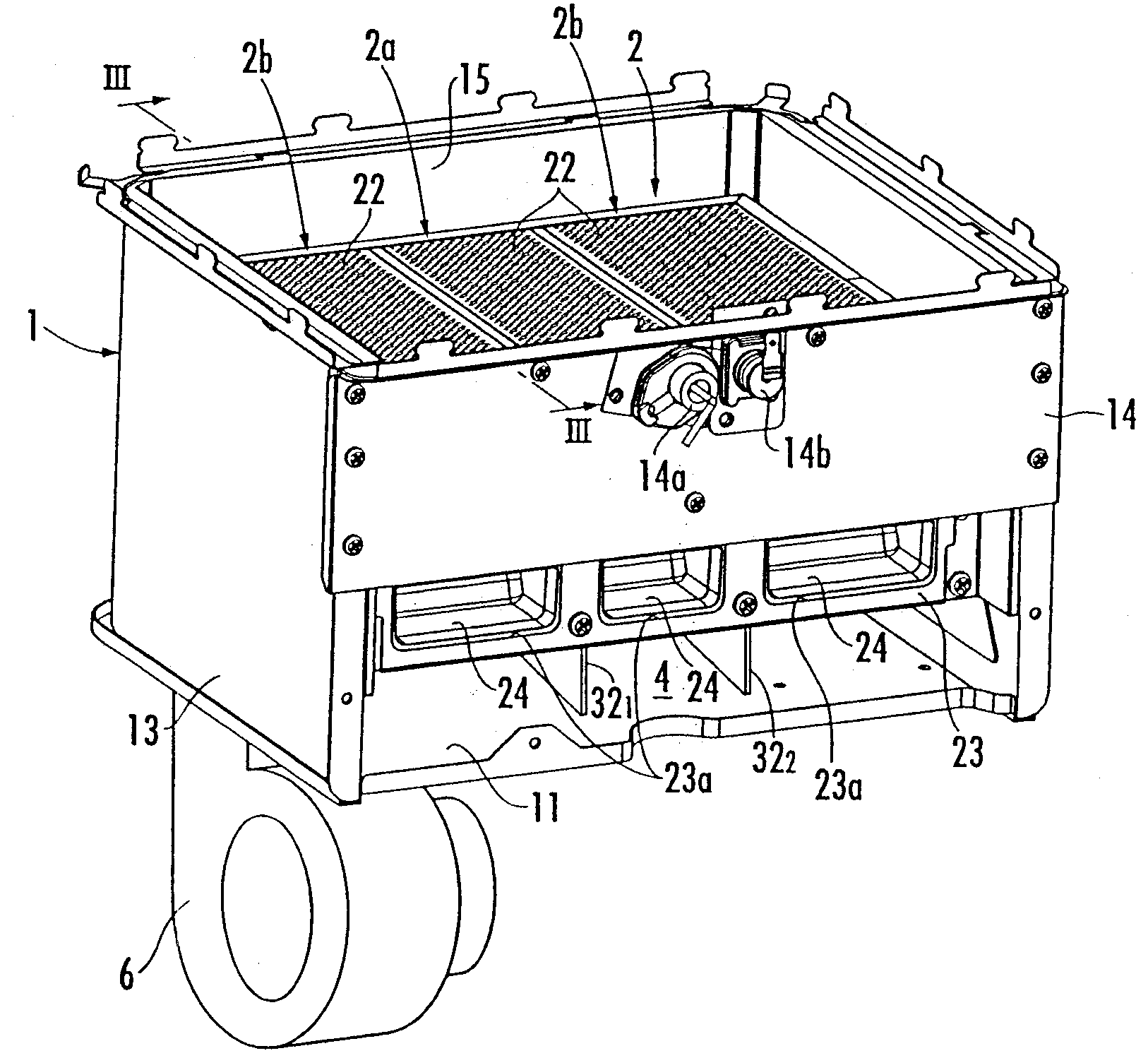
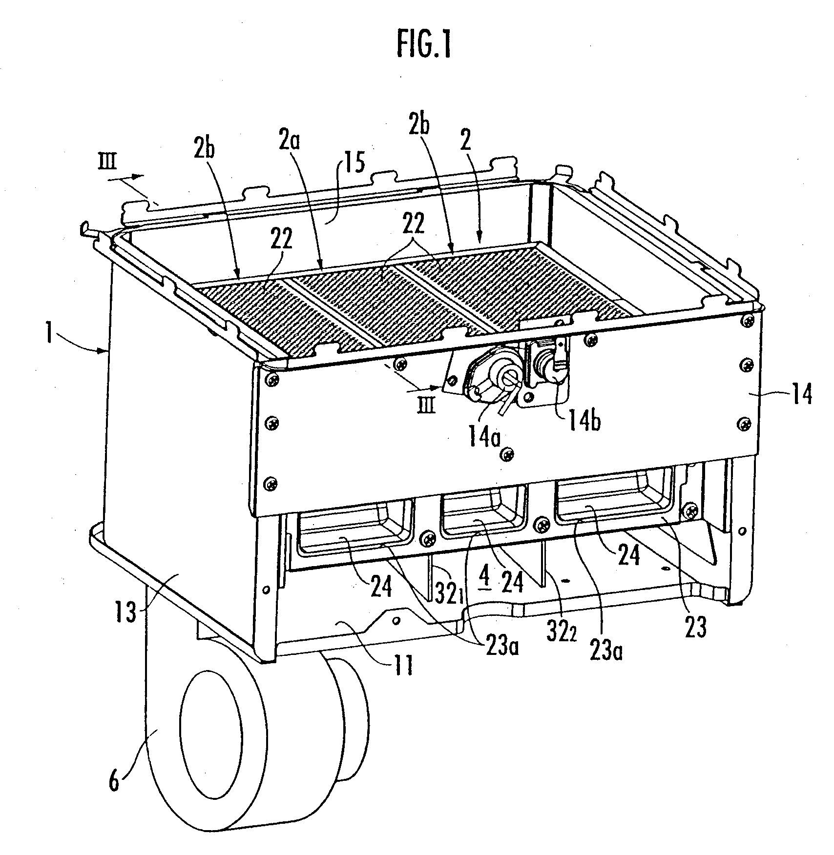
[0019]Referring to FIGS. 1 and 2, reference numeral 1 denotes a combustion housing in which an object to be heated (not shown) such as a heat exchanger for hot water supply is arranged in an upper part thereof. A burner unit 2 is arranged in the combustion housing 1.

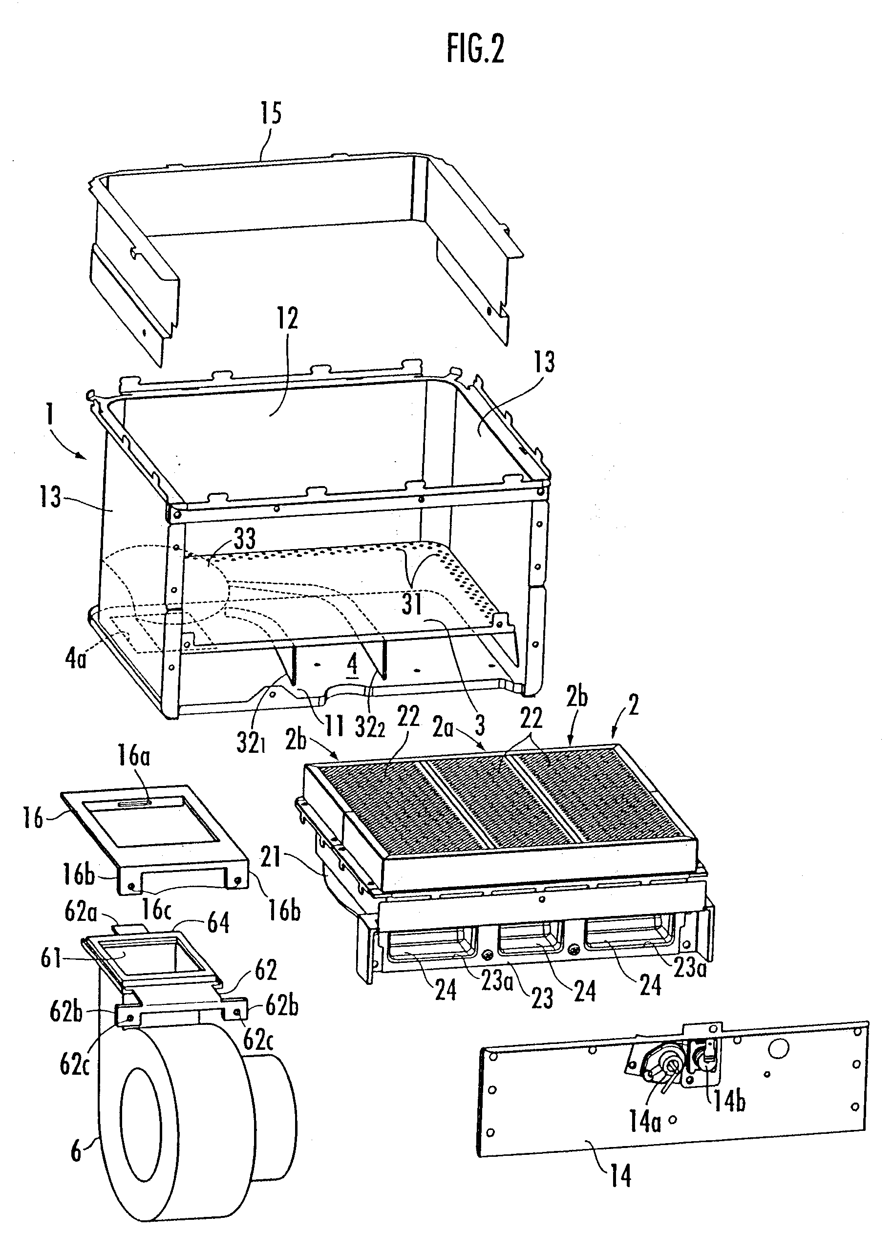
[0020]The combustion housing 1 includes a bottom plate 11, and also includes a rear plate 12 and left and right side plates 13, each of which is formed by bending one plate material, a front plate 14 attached to an upper part between front ends of both the side plates 13, and a heat shield plate 15 that covers upper inner side surfaces of the rear plate 12 and both the side plates 13. An ignition plug 14a and a flame detecting element 14b such as a flame rod are attached to the front plate 14.

[0021]In the combustion housing 1, an air supply chamber 4 in a lower part partitioned by a partition plate 3 from an arrangement section of the burner unit 2 and a primary air chamber 5 that stands from a front end of the air suppl...


PUM


Abstract

In a combustion apparatus in which an air supply chamber 4 in a lower part partitioned by a partition plate 3 from an arrangement section of a burner unit and a primary air chamber in a front part that stands from a front end of the air supply chamber are provided in a combustion housing 1 incorporating the burner unit 2, the air from a combustion fan 6 connected to an air supply port 4a opened on a bottom surface of the air supply chamber flows to the primary air chamber through the air supply chamber, and primary air is supplied from the primary air chamber to respective burners of the burner unit, it is an object of the present invention to make it possible to uniformalize a pressure distribution in the primary air chamber and supply the primary air to all the burners equally. To attain the object, a plurality of projected rims 321 and 322 extending from the periphery of a portion of the partition plate 3 opposed to the air supply port 4a to a front edge of the partition plate 3 are provided on a lower surface of the partition plate 3. The height of a downward projection of the projected rims 321 and 322 is reduced toward the air supply port 4a. The portion of the partition plate 3 opposed to the air supply port 4a is formed in a concave shape recessed upward.

Description

BACKGROUND OF THE INVENTION[0001]1. Field of the Invention[0002]The present invention relates to a forced air supply combustion apparatus that supplies primary air with a combustion fan.[0003]2. Description of the Related Art[0004]Conventionally, as a combustion apparatus of this type, there is known a combustion apparatus in which, in a combustion housing, a burner unit including a plurality of burners provided side by side in the horizontal direction is arranged and an air supply chamber in a lower part partitioned by a partition plate from an arrangement section of the burner unit and a primary air chamber in a front part that stands from a front end of the air supply chamber are provided, the air from a combustion fan, which is connected to an air supply port opened on a bottom surface of the air supply chamber, flows to the primary air chamber through the air supply chamber, and the primary air is supplied from the primary air chamber to the respective burners of the burner uni...

Claims


Application Information

Patent Timeline
IPC IPC(8): F23C5/08
CPCF23D14/36
Inventor OJIRO, TAKASHITAKASU, YOSHIHIKO
Owner RINNAI CORP
Why Eureka
Try Eureka