Catheter Position Tracking for Intracardiac Catheters

a catheter and position tracking technology, applied in the field of catheter position tracking, can solve the problems of limited tools, limited view, and limited view of the current tomographic plan

Inactive Publication Date: 2008-06-19
ST JUDE MEDICAL ATRIAL FIBRILLATION DIV
View PDF13 Cites 150 Cited by
  • Summary
  • Abstract
  • Description
  • Claims
  • Application Information

AI Technical Summary

Benefits of technology

[0010]The various embodiments herein provide an apparatus and methods for tracking movement of one or more points of a catheter by using accelerometers deployed at one or more points within the body of the catheter, including parts of the catheter deployed within the body as well as parts of the catheter deployed outside the body. The relative position of the imaging probe is then tracked by constantly monitoring the acceleration of these sensors as a function of time and using this data to calculate displacement from a baseline position.

Problems solved by technology

These tools are limited, however, in their ability to provide a comprehensive view of the underlying anatomy, and their ability to accurately track and display a plurality of moving structures and instruments, such as valves and catheters, that might be required for diagnostic or treatment purposes.
2-dimensional (2-D) images provided by known ultrasound imaging systems limit viewing to the tomographic plane currently being imaged and do not provide optimal views of structures or instruments that are not coplanar to the tomographic plane.
Although 3-D reconstruction of general ultrasonic and echocardiography images is common in the field of conventional (i.e., non-catheter) ultrasound imaging, the reconstruction of 3-D ultrasonic images using catheter based transducers has proven to be a technological challenge.
Current catheter tracking systems common in the art, such as the use of ultrasonic ranging, use of electromagnetic fields, or body electrical impedance techniques, can be quite complicated to engineer.
In particular, challenges exist in determining the rotational position of a side-firing phased array catheter with sufficient accuracy to enable reconstructing a clinically useful 3-D image.
Such techniques limit the ability of the physician to manipulate the catheter while adding complexity and risk to the overall patient safety and efficacy situation.
However, given the severe size limitations of catheters and associated element limitations, optimal image quality has not been achieved using such techniques.

Method used


Image

  • Catheter Position Tracking for Intracardiac Catheters
  • Catheter Position Tracking for Intracardiac Catheters
  • Catheter Position Tracking for Intracardiac Catheters

Examples


Embodiment Construction

[0026]Reference will now be made in detail to exemplary embodiments of the present invention. Wherever possible, the same reference numbers will be used throughout the drawings to refer to the same or like parts.

[0027]As used herein, the terms “about” or “approximately” for any numerical values or ranges indicates a suitable dimensional tolerance that allows the part or collection of components to function for its intended purpose as described herein. Also, as used herein, the terms “patient”, “host” and “subject” refer to any human or animal subject and are not intended to limit the systems or methods to human use, although use of the subject invention in a human patient represents a preferred embodiment.

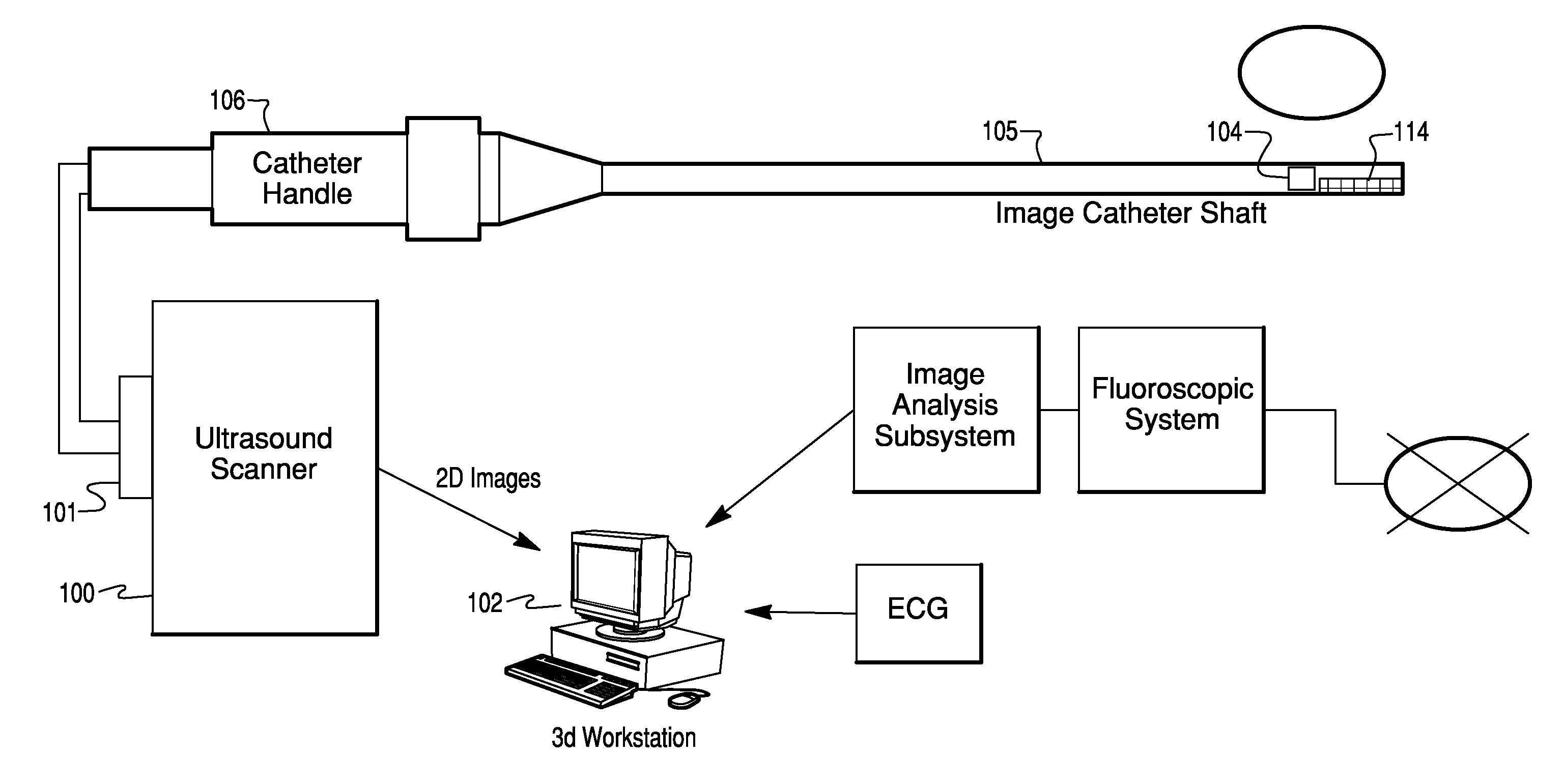
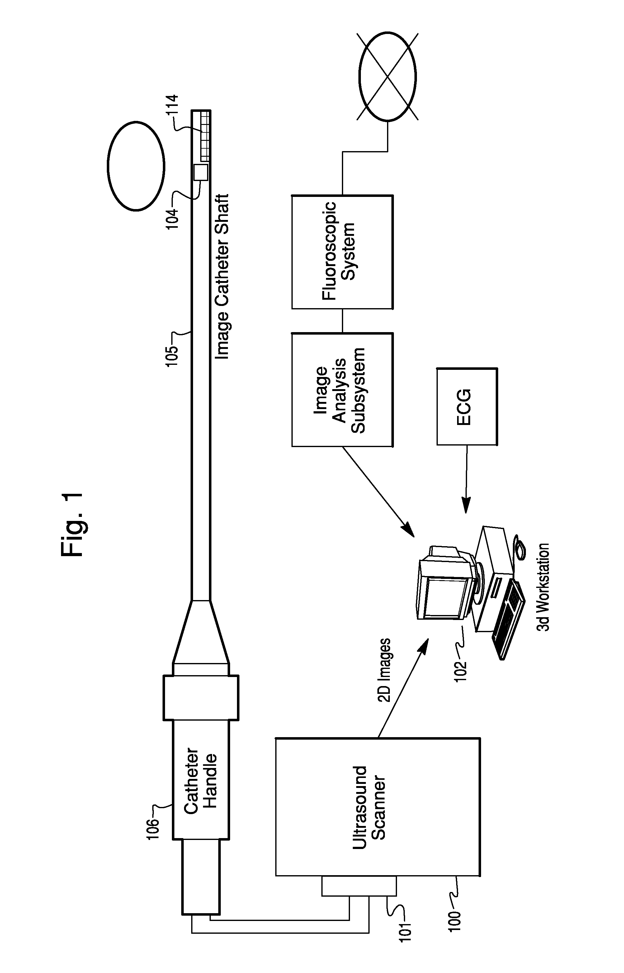
[0028]An exemplary ultrasound imaging system usable with various embodiments of the present invention is shown in the block diagram of FIG. 1. The imaging system includes an ultrasound imaging device 100, which could include within it an image processing workstation 102. The ultras...


PUM


Abstract

An ultrasound imaging system includes one or more accelerometers positioned near the imaging transducer. Acceleration data from the accelerometers are used to estimate the position of the imaging transducer. By combining position information calculated based on acceleration data with position information obtained by other methods, the imaging transducer position can be determined more accurately and closer in time to when images are obtained. The resulting accurate imaging transducer position information enables combining multiple images from different positions or orientations to generate multi-dimensional images.

Description

BACKGROUND OF THE INVENTION[0001]1. Field of the Invention[0002]The present invention relates generally to tracking the position of catheters used in medical procedures that are introduced into the human body, and more particularly to a method and apparatus for tracking ultrasound imaging catheters to ascertain image plane orientation and position.[0003]2. Description of the Related Art[0004]Ultrasound devices have been developed and refined for the diagnosis and treatment of various medical conditions. Such devices have been developed, for example, to track the magnitude and direction of motion of moving objects, and / or the position of moving objects over time. By way of example, Doppler echocardiography is one ultrasound technique used to determine motion information from the recording and measurement of Doppler data for the diagnosis and treatment of cardiac conditions, and is described in U.S. Patent Application Publication No. 20040127798 of U.S. application Ser. No. 10 / 620,517...

Claims


Application Information

Patent Timeline
Patent Type & Authority Applications(United States)
IPC IPC(8): A61B8/00
CPCA61B8/12A61B8/4254G01S15/8993A61B2562/0219G01S7/52088A61B8/483
Inventor DALA-KRISHNA, PRAVEEN
Owner ST JUDE MEDICAL ATRIAL FIBRILLATION DIV
Why Eureka
Try Eureka