Blood pressure measuring device
- Summary
- Abstract
- Description
- Claims
- Application Information
AI Technical Summary
Benefits of technology
Problems solved by technology
Method used
Image

Examples
first embodiment
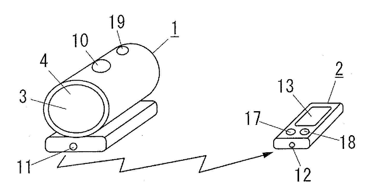
[0023]As shown in FIG. 1 and FIG. 2, the blood pressure measuring device in accordance with a first embodiment of the present invention has a main device 1, and a separate device 2 which can be used separately from the main device 1. As described in detail later, the separate device 2 of this embodiment is configured to be turned on in conjunction with the main device 1.
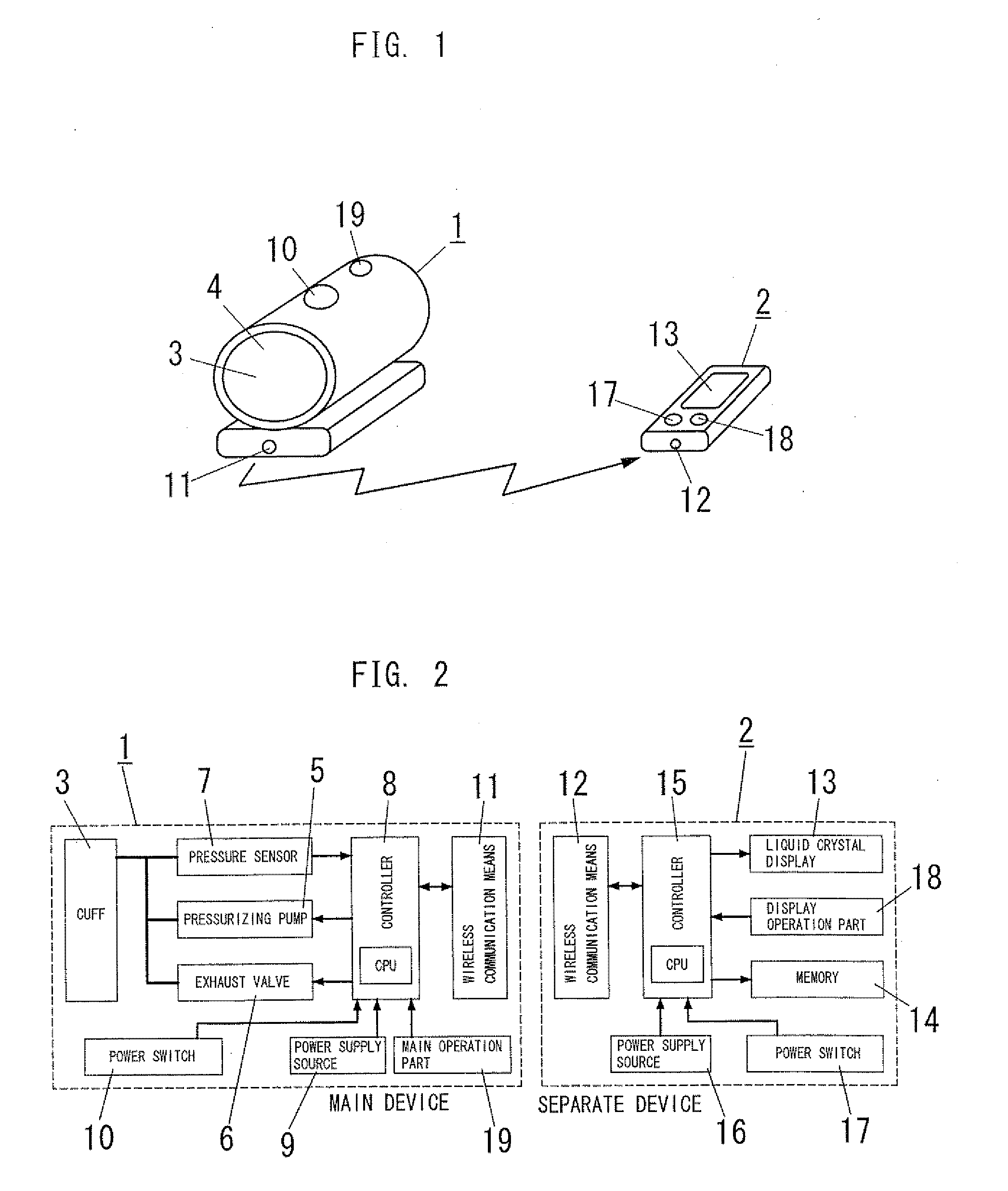
[0024]The main device 1 includes a through hole 4 though which an arm of a user is inserted. Furthermore, the main device 1 includes a cuff 3 which is disposed along an inner surface of the through hole 4 and is for constricting a blood flow, a pressurizing pump 5 (a pressurizing means) for inflating (pressurizing) the cuff 3, an exhaust valve 6 for exhausting air from the cuff 3, a pressure sensor 7 for detecting a pressure of the cuff 3, a main operation part 19 for providing instructions to the main device 1 from outside to perform a blood pressure measurement, and a controller 8 for controlling the pressurizing p...
second embodiment
[0037]The basic composition of the blood pressure measuring device of a second embodiment is identical to the first embodiment, so similar parts to the first embodiment are identified by the same reference character and no duplicate explanation is made here.
[0038]In this embodiment, the method of the wireless communication between the main device 1 and the separate device 2 performed when the main device 1 and the separate device 2 are activated is different from that of the first embodiment. The wireless communication means 11 of the main device 1 and the wireless communication means 12 of the separate device 2 of this embodiment have a two-way communication function which transmits data in both directions.
[0039]Hereinafter, the method of the wireless communication between the main device 1 and the separate device 2 of this embodiment on start-up will be described in detail with reference to FIG. 5.
[0040]As shown in FIG. 5, as is the case with the first embodiment, when the separat...
third embodiment
[0046]The basic composition of the blood pressure measuring device of a third embodiment is identical to the first and second embodiments, so similar parts to these embodiments are identified by the same reference character and no duplicate explanation is made here.
[0047]In the first embodiment, both of the main device 1 and the separate device 2 have a power switch, respectively, but in this embodiment, as shown in FIG. 6A, only the separate device 2 has a power switch 17 (that is, in this embodiment, “one device” of claim 1 is the separate device 2, and “the other device” is the main device 1.)
[0048]In this embodiment, as is the case with the second embodiment, the wireless communication means 11 of the main device 1 and the wireless communication means 12 of the separate device 2 have a two-way communication function.
[0049]When the power switch 17 of the separate device 2 is pushed when the separate device 2 is in the power-off state, the separate device 2 is activated, and the s...
PUM
 Abstract
Description
Claims
Application Information
 - Generate Ideas
- Intellectual Property
- Life Sciences
- Materials
- Tech Scout
- Unparalleled Data Quality
- Higher Quality Content
- 60% Fewer Hallucinations
Browse by: Latest US Patents, China's latest patents, Technical Efficacy Thesaurus, Application Domain, Technology Topic, Popular Technical Reports.
© 2025 PatSnap. All rights reserved.Legal|Privacy policy|Modern Slavery Act Transparency Statement|Sitemap|About US| Contact US: help@patsnap.com