Method and apparatus for deflecting a screw-in lead

Active Publication Date: 2008-06-19
MEDTRONIC INC
View PDF19 Cites 8 Cited by
  • Summary
  • Abstract
  • Description
  • Claims
  • Application Information

AI Technical Summary

Benefits of technology

[0008]The present invention is directed toward providing a deflectable stylet system particularly optimized for use in conjunction with a lead of the type having a fixation helix, in which the fixation helix is screwed into body tissue by rotation of the connector pin of the lead. In particular, the invention is intended to provide a deflectable stylet system that allows for differences in length from lead to lead and also provides an easy mechanism for adjusting the position of the stylet within the lead body.
[0010]When the attachment is coupled to the lead, the attachment may be rotated to screw the fixation helix into body tissue, configured such that the knob and the lead to which it is attached may readily be moved longitudinally relative to the remainder of the deflectable stylet handle. In a preferred embodiment, the attachment includes a knob with a recess at its distal end for engaging the connector pin of a lead and an elongated tubular extension at its proximal end, slidably inserted into a corresponding distally facing recess in a deflectable stylet handle. In a more preferred embodiment, the distally facing recess in the stylet handle is formed within the spinner or knob of a deflectable stylet handle generally as disclosed in the above cited Greene et al application. The proximally directed extension on the attachment's knob allows for it to be moved longitudinally relative to the stylet handle, in turn allowing for longitudinal movement of the lead relative to the deflectable stylet.
[0011]In one preferred embodiment, the deflectable stylet assembly is also provided with a tubular pin, mounted around the proximal portion of the flexible stylet and mounted in fixed longitudinal relationship with the stylet handle. This tubular pin may engage the interior of the proximally directed tubular extension of the attachment, providing for an additional mechanism to allow longitudinal movement of the attachment knob relative to the deflectable stylet handle, while retaining appropriate alignment of the attachment knob and stylet handle to allow for rotation of the attachment knob. In some embodiments, a bushing may be provided within the attachment to facilitate the free rotation of the attachment around the tubular pin. The attachment may be slip-fit to the tubular pin in a manner that provides for controlled longitudinal repositioning of the attachment with respect to the stylet assembly. The attachment may also be adapted to rigidly couple to the tubular pin at predetermined positions on the pin.

Problems solved by technology

The spinner ball, as described, however, does not allow compensation for variations in lead length or allow for ready adjustment of the position of the stylet within the lead body.

Method used


Image

  • Method and apparatus for deflecting a screw-in lead
  • Method and apparatus for deflecting a screw-in lead
  • Method and apparatus for deflecting a screw-in lead

Examples


Embodiment Construction

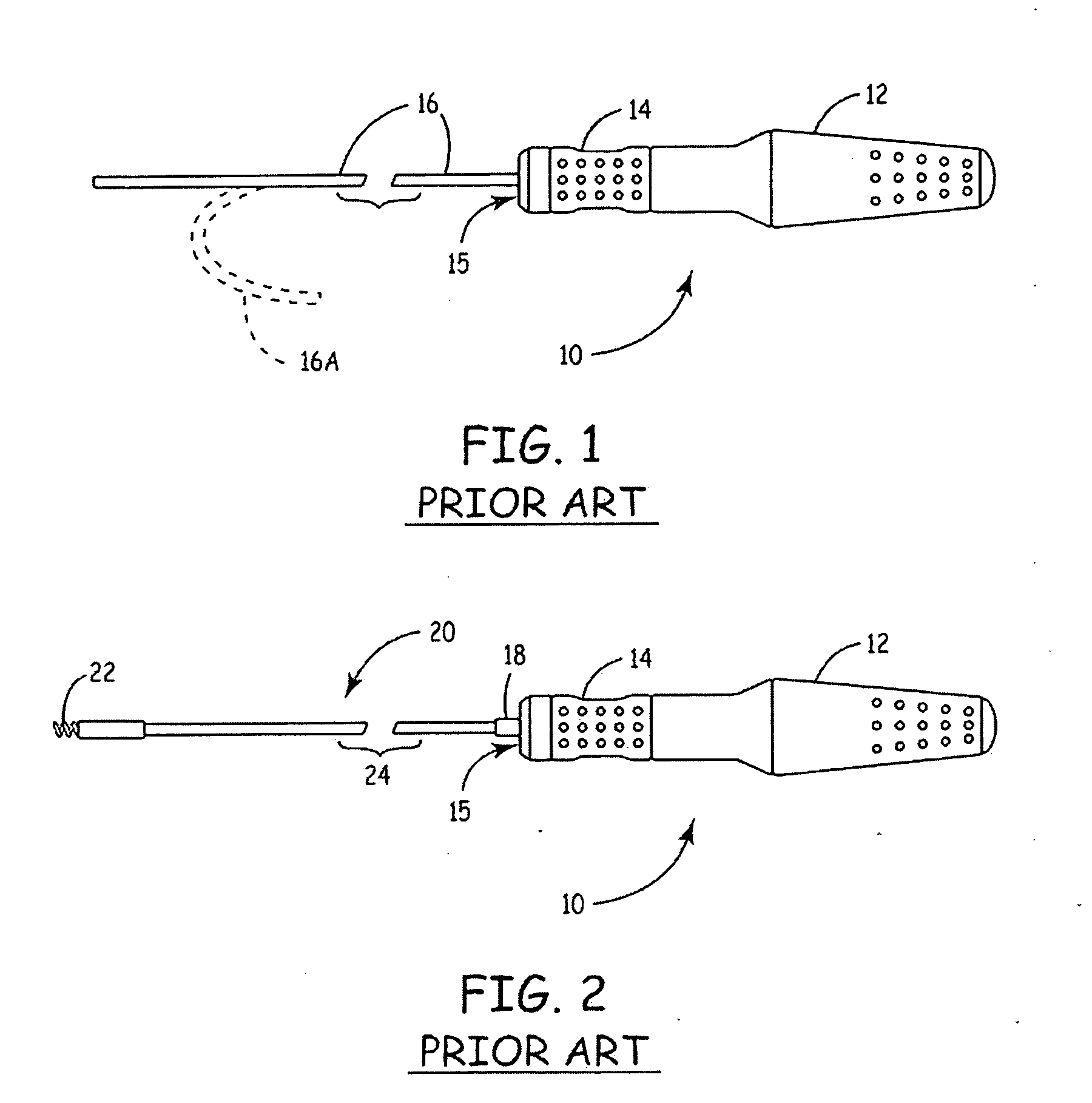
[0020]FIG. 1 illustrates a plan view of a prior art deflectable stylet, similar to that employed in conjunction with the present invention. The deflectable stylet 16 is provided with a control handle assembly 10 provided with a handle 12 and a deflection control which takes the form of a spinner or knob 14, mounted rotatably and slidably with respect to the handle portion 12. The handle 12 is provided with indentations at its proximal end, as is the spinner or knob 14 to assist the physician in maintaining a grip. Ribbing, knurling or other texturing could of course be substituted. The deflectable stylet 16 exits from a distal recess 15, within spinner or knob 14. The rotation of spinner or knob 14 causes deflection of the distal portion of stylet 16 to a curved configuration as illustrated at 16A.

[0021]Deflectable stylet 16 may take the form of any known deflectable stylet employing an outer tubular member and an inner tension wire which, when it applies tension to the distal tip o...


PUM


Abstract

A deflectable stylet system optimized for use in conjunction with a lead of the type having a fixation helix that is screwed into body tissue by rotation of the lead's connector pin is disclosed. The system includes an attachment that is rotatable and longitudinally slidable with respect to the handle of a deflectable stylet. A lead coupled to the attachment may be moved longitudinally with respect to a stylet to account for slight variances in the lead length. In one embodiment, the attachment couples to the lead via a pushbutton mechanism that can be locked to the lead using one hand. The attachment may be rotated to thereby rotate the lead connector. This allows for retraction and extension of a retractable fixation helix, and for further attachment or detachment of a fixation helix to adjacent tissue. In one embodiment, the attachment may be longitudinally rigidly positioned in predetermined locations with respect to the handle. According to another aspect of the system, a deflection device is coupled to the handle to facilitate deflection of the stylet. In one embodiment, this deflection device may be rotatably and / or slidably activated to accomplish the stylet deflection. The system allows a user to adjust lead length with respect to the stylet length, and to further perform stylet deflection and lead rotation all with one hand.

Description

CROSS REFERENCE TO PRIORITY APPLICATION[0001]This application is a continuation of U.S. patent application Ser. No. 10 / 844,746, filed May 13, 2004; which is a divisional of U.S. patent application Ser. No. 09 / 659,797, filed Sep. 12, 2000; both of which are herein incorporated by reference in their entirety.CROSS REFERENCE TO COMMONLY-ASSIGNED PATENTS[0002]Reference is made to commonly-assigned U.S. Pat. No. 6,059,482, filed May 29, 1998, by Baumann; and to commonly-assigned U.S. Pat. No. 6,027,462 issued to Greene et al, which have related subject matter.BACKGROUND OF THE INVENTION[0003]The present invention relates generally to implantable leads and catheters and more particularly to mechanisms for deflecting implantable leads and catheters to assist in guiding them through the vascular system.[0004]Over the years, quite a number of mechanisms have been disclosed and employed to deflect catheters and implantable leads. These have taken the form of deflectable guidewires and deflect...

Claims


Application Information

Patent Timeline
IPC IPC(8): A61M25/09A61M25/01A61N1/05
CPCA61M25/0136A61N2001/058A61N1/0573
Inventor GARDESKI, KENNETH C.POOR, CORINNE A.G.CLEMENS, WILLIAM J.ODEGARD, JEREMY J.
Owner MEDTRONIC INC
Why Eureka
Try Eureka