
Clinical and Surgical System and Method for Moving and Stretching Plastic Tissue

a plastic tissue and surgical system technology, applied in the field of systems and methods for moving and stretching plastic tissue, can solve the problems of poor force distribution across the tissue, inability to adjust the force exerted by the suture, and rudimentary coupling work poorly, etc., to achieve simple or complex geometry, simple or complex structure, and constant force or tension

Inactive Publication Date: 2008-06-19
CANICA DESIGN
View PDF91 Cites 65 Cited by
  • Summary
  • Abstract
  • Description
  • Claims
  • Application Information

AI Technical Summary

Benefits of technology

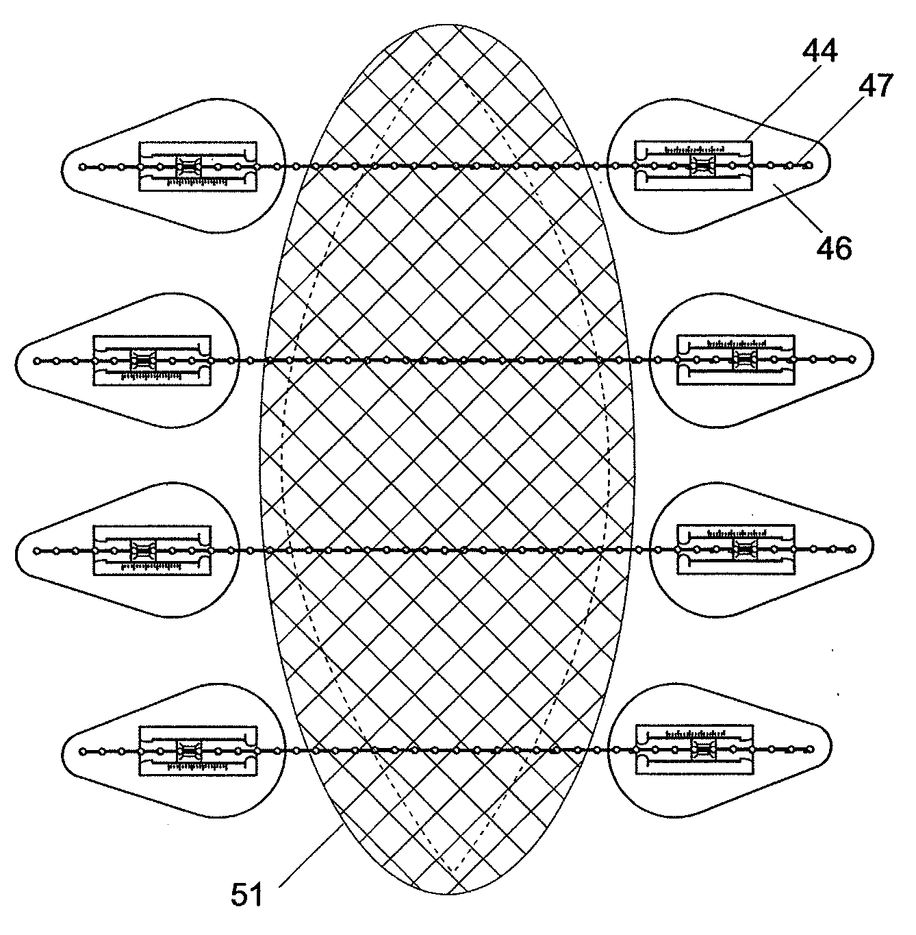
[0014]This invention provides manipulation and control of tissue positions and tensions on a living person or animal, utilizing both tissue stretch and creep to restore and move any plastic tissues. This invention provides methods and devices for moving and stretching plastic tissue that are simple, easy to use, relatively inexpensive, extremely versatile, self-adjusting and capable of exerting relatively constant force or tension over a variety of distances and at various intersecting angles in wounds having simple or complex geometry.
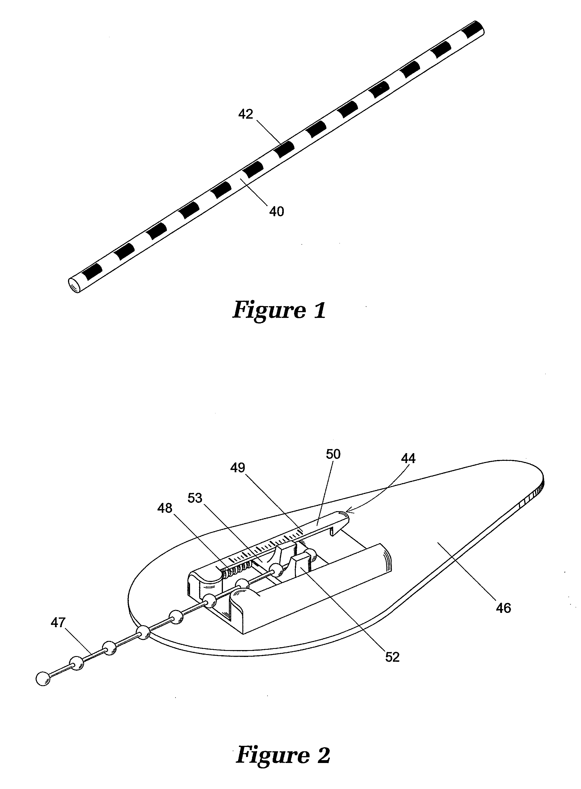
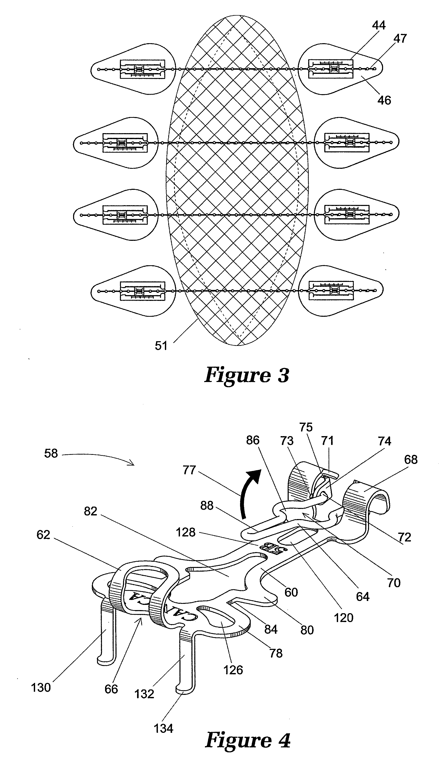
[0018]The anchors of this invention generally separate the tissue coupling structure from the structure for attaching to a force applying component, thereby permitting optimization of each of the two anchor structures and adaptation of each anchor structure to a variety of different situations. The anchor structures of this invention for coupling to force applying components permit quick, easy attachment and reattachment of various facs, particularly including facs made of silicone, which is extremely difficult to secure. The tissue coupling structures and techniques of this invention include invasive structures such as flukes, staples and sutures, and tissue penetration by the force applying component. The tissue coupling structures also include non-invasive structures utilizing adhesive on plates and fabrics, among other alternatives.
[0021]This invention displays several critical advantages over existing systems. Human skin varies dramatically in elasticity and thickness depending on age and health. Unhealthy patients, such as oncology patients, often present with compounding maladies such as thin, friable and ischemic skin at retracted wounds from procedures, such as a mastectomy, where a retracted incision is further irritated by radiation, which significantly weakens the skin. In one embodiment of this invention, a variety of attachment structures match the tissue bonding strength to the required moving and stretching force to minimize necrosis and scaring. Additionally, various force distributing components may be used in a multitude of ways to create a broad range of moving and stretching forces that match the counter-tractive tensions on multiple planes present in various locations, and may vary in thickness and cross section to achieve a near infinite range of tension as required. Unlike some prior devices, an overhead beam is not required, and therefore this invention is capable of providing linear, radial, and circumferencial force exerted on multiple points.
[0023]Systems of this invention allow rapid removal for dressing changes and uninterrupted visualization of the wound bed during routine cleaning procedures. When tension adjustment is required, it can be accomplished quickly, and the force applying components can include an easily read indicator. Thus, the nursing staff may replace wound dressings and readily reapply the force specified by the surgeon.
[0024]Utilizing dynamic force to move and stretch tissue offers the advantage of a relentless countertraction force, while allowing for expansion and contraction of the wound site, which greatly enhances patient mobility and is compliant with respiratory movements. In addition, an increased range of traction beyond the elasticity of the skin itself is provided. For example, a range of closure rates of 1.25 to 1.75 cm per day may be averaged over the course of treatment, which is considerably faster (about twice as fast) as the rates achieved using static counter traction methods of the prior art.

Problems solved by technology

However, such rudimentary coupling works poorly for several reasons, importantly including the extremely poor force distribution across the tissue and the absence of any practical means for adjusting the force exerted by the suture over a period of time.

Method used


Image

  • Clinical and Surgical System and Method for Moving and Stretching Plastic Tissue
  • Clinical and Surgical System and Method for Moving and Stretching Plastic Tissue
  • Clinical and Surgical System and Method for Moving and Stretching Plastic Tissue

Examples


Embodiment Construction

I. Force Applying Components

[0043]Force applying components of this invention can integrate energy storage and force transmission, such as in an elastomeric rod, or can separate energy storage and transmission as in a spring connected to a cable.

[0044]A. Integrated Force Applying Components

[0045]An integrated force applying component according to this invention may be formed in rods, cords, bands, loops, sheets, nets, wires, strands, cables, tubes or other suitable structure. In one embodiment, the fac is an elastic tube that flattens out at the point of maximum load and becomes load dissipating. This tubular force applying component may be adapted to slide over the end of a trocar, allowing the force applying component to be driven through the tissue. For example, a force applying component may be driven through the wound edge using a trocar to prevent eversion. In an alternative embodiment, a rod-shaped force applying component is driven through the tissue using a needle swaged on...


PUM


Abstract

A system and method of moving and stretching plastic tissue using dynamic force. A preferably non-reactive force applying component is adjustably attachable to one or more tissue attachment structures for securing the force applying component to the plastic tissue, providing a self adjusting system that is capable of exerting relatively constant tension over a certain distance.

Description

RELATED APPLICATION DATA[0001]This application is a continuation-in-part of International Application No. PCT / IB01 / 00796, filed Nov. 15, 2001, published in English under publication no. WO 01 / 85035.FIELD OF THE INVENTION[0002]This invention relates generally to systems and methods for moving and stretching plastic tissue and more particularly to systems and methods for moving and stretching such tissue that exert a relatively constant tension over a given distance and that are easily adjustable.BACKGROUND[0003]In general, surgery and surgical treatment involve one or both of tissue separation and tissue joining. In surgery, medical treatment, and medical research, it is desirable to retract tissue, stabilize tissue, and present tissue in a variety of specific orientations to provide access to the area under investigation or repair, ideally in a method that creates minimal trauma beyond what is necessary for exposure and visualization of the operative area. In other words, it is desi...

Claims


Application Information

Patent Timeline
Patent Type & Authority Applications(United States)
IPC IPC(8): A61B17/03A61B17/02A61B17/08
CPCA61B17/02A61B17/085A61B17/08
Inventor O'MALLEY, MICHAEL T.BELL, MICHAEL S.G.MAXWELL, TIMOTHYHENDERSON, JAMES
Owner CANICA DESIGN
Learn More