Infrared burner with exhaust gas flue

Inactive Publication Date: 2008-06-26
BSH HOME APPLIANCES CORP
View PDF12 Cites 0 Cited by
  • Summary
  • Abstract
  • Description
  • Claims
  • Application Information

AI Technical Summary

Benefits of technology

[0004]It is accordingly an object of the present invention to provide an infrared burn

Problems solved by technology

Often, unburned gas and combustion residue can col

Method used


Image

  • Infrared burner with exhaust gas flue
  • Infrared burner with exhaust gas flue
  • Infrared burner with exhaust gas flue

Examples


Embodiment Construction

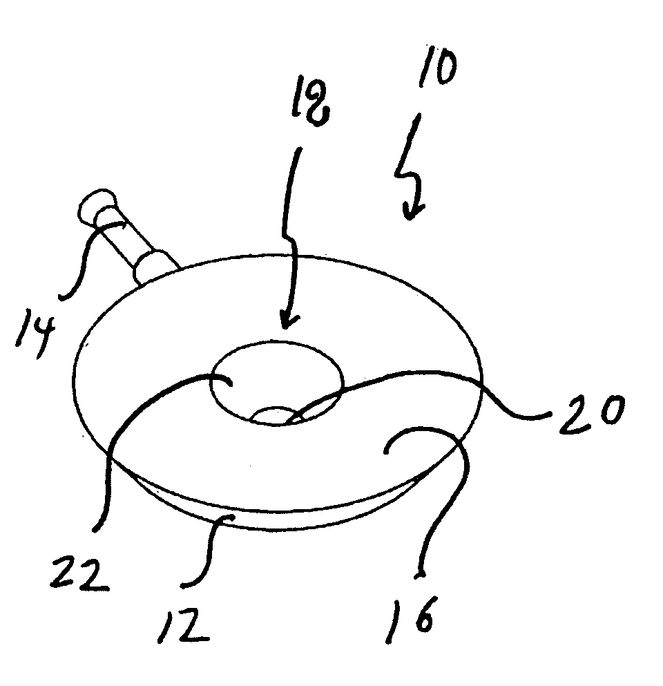
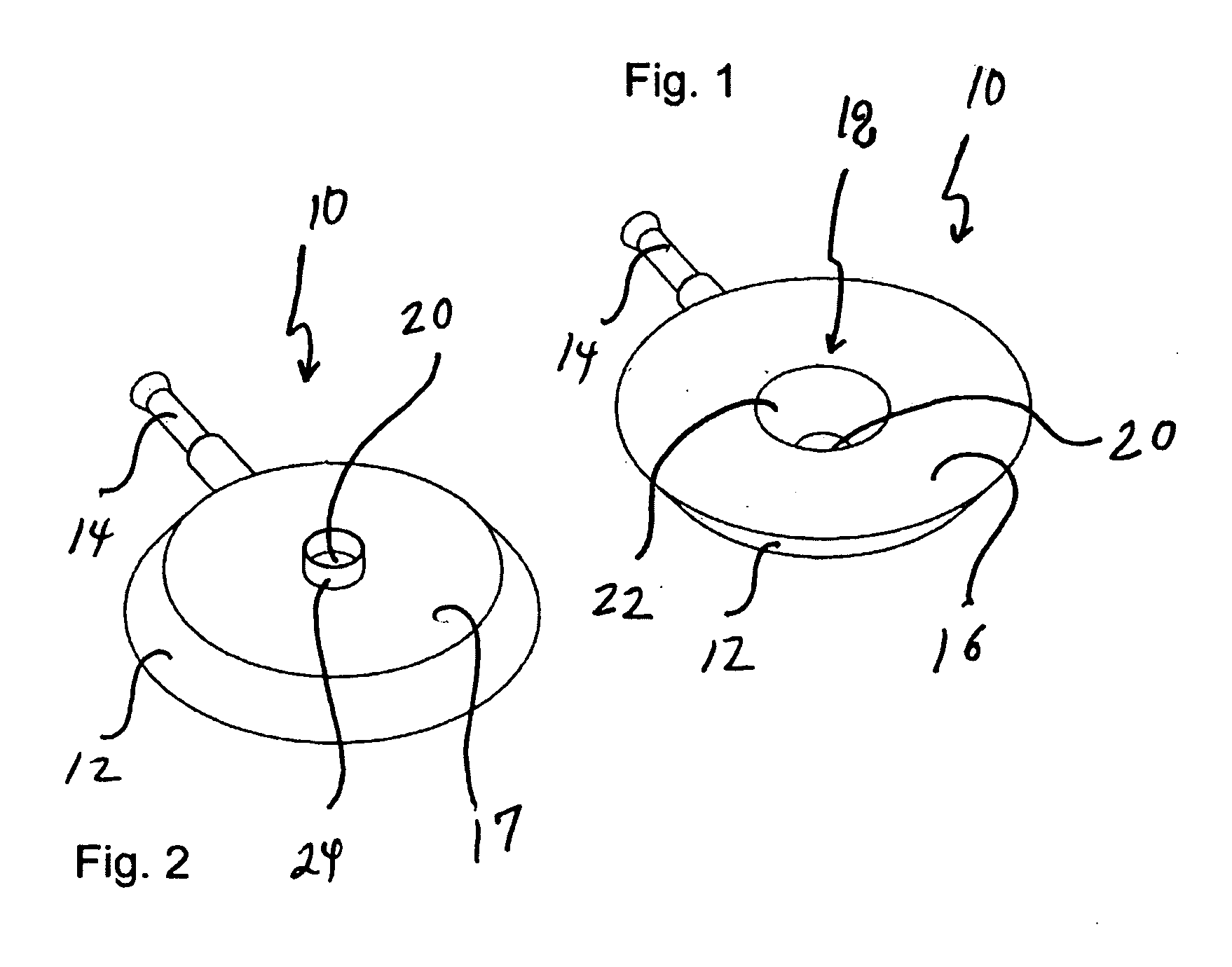
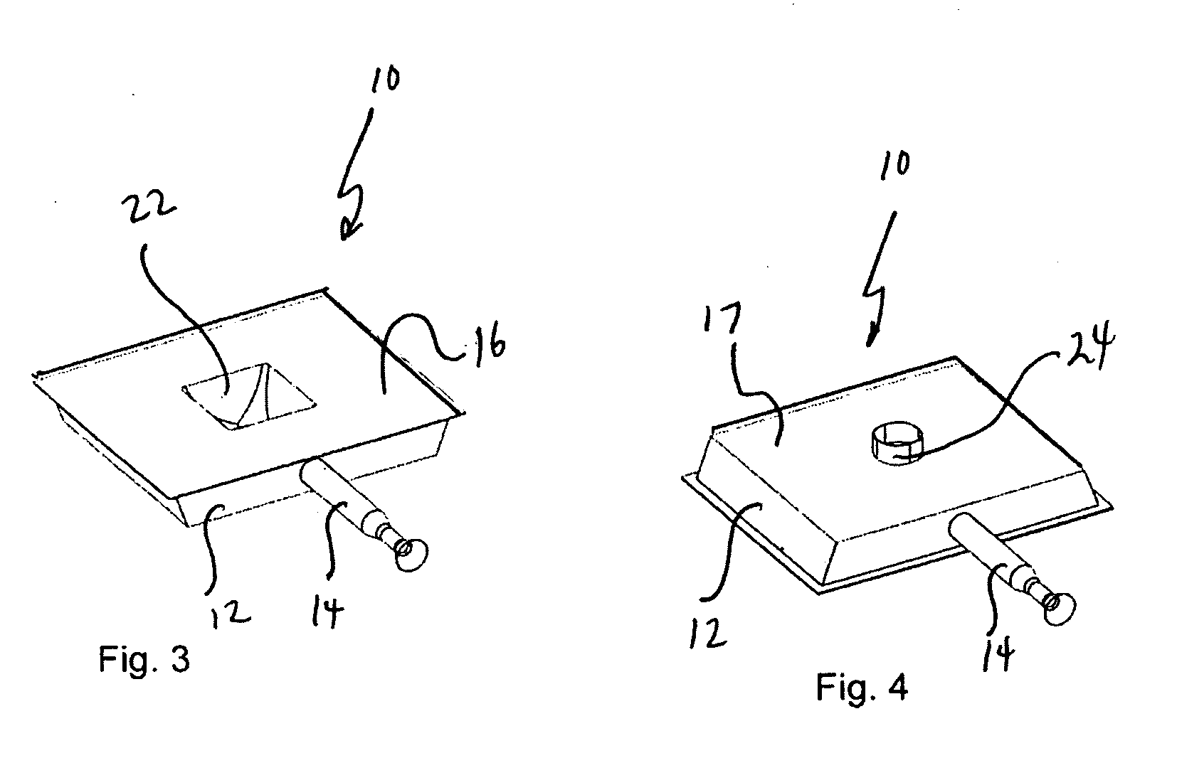
[0010]Turning now to the drawings and, more particularly to FIG. 1, an infrared burner is illustrated generally at 10 and includes a generally circular burner body 12 having a burner top 16 and a burner bottom 17 attached thereto as seen in FIGS. 1 and 2. The result is a washer-like structure with tapered side walls wherein the major and minor diameters of the burner top 16 are larger than the major and minor diameters of the burner bottom 17. A gas feed pipe 14 projects outwardly from one portion of the burner body 12. The burner body 12 defines gas passageways therein (not shown).

[0011]A central area 18 is defined by the central openings within the burner top 16 and burner bottom 17. The opening of the burner bottom 17 is an exhaust opening 20. Walls 22 are formed on the inside of the central area and are tapered from the larger central area opening to the smaller exhaust opening 20. The walls 22 of the central area 18 act like a nozzle and if a draft is drawn through the central ...


PUM


Abstract

An infrared range burner having a plurality of gas passageways formed therein for delivering combustion gas from a central gas supply to individual burner jets, the range burner including a burner body formed as a closed loop defining an open central area, the burner body having a plurality of gas passageways formed therein; a burner top disposed on the burner body and including burner jets in communication with the gas passageways;
    • a burner bottom having an exhaust opening formed in a central area thereof, the burner bottom being disposed on the burner body oppositely from the burner top, with the open central area in registry with the exhaust opening and extending between the burner top and the burner bottom; and a flue mounted to the burner bottom and projecting outwardly therefrom, the flue being in fluid communication with the exhaust opening for drawing exhaust gases from the open central area.

Description

BACKGROUND OF THE INVENTION[0001]The present invention is related broadly to cooktops having infrared gas burners including barbeque grills and, more particularly to an infrared gas burner having an exhaust gas flue.[0002]Infrared burners work by focusing the flame of a standard gas burner onto a ceramic tile having thousands of microscopic holes in it. This converts the heat of the flame into infrared, radiant energy. The heat energy is much greater and more persistent than a standard grill can produce. Infrared burners can reach cooking temperatures greater than 1800 degrees Fahrenheit.[0003]Some infrared burners include burner bodies formed as a perimetorial structure or a loop, be it round, square or other closed loop shape. Such closed loop burners define an open central area in the middle of the burner. Often, unburned gas and combustion residue can collect in the atmosphere in the center of the burner. It would be advantageous to evacuate the central area as quickly and effic...

Claims


Application Information

Patent Timeline
IPC IPC(8): F24C15/10
CPCF23D14/14F23D14/126
Inventor DYSINGER, DAVIDHENDRICKS, DONALDKOLODY, TIMOTHY
Owner BSH HOME APPLIANCES CORP
Why Eureka
Try Eureka