Indexable stump cutter tooth

a stump cutter and indexing technology, applied in the field of stump cutters, can solve the problems of stump cutter teeth, stump cutter teeth, and supporting structures (i.e., pockets), and can experience catastrophic breakage, and become worn past the point of usefulness

Active Publication Date: 2008-06-26
KENNAMETAL INC +1
View PDF22 Cites 43 Cited by
  • Summary
  • Abstract
  • Description
  • Claims
  • Application Information

AI Technical Summary

Benefits of technology

[0009]In one form thereof, the invention is a stump cutter tooth held by a pocket member, which has a first edge and a second edge, wherein the pocket member is operatively attached to a driven wheel, which has opposite first and second side surfaces. The stump cutter tooth comprises an elongate tooth body that has an axial forward end, a first hard region that is at the axial forward end of the tooth body and defines at least one distinct cutting edge that has an orientation to engage the stump during operation of the driven wheel. The stump cutter tooth has a second hard region that is at the axial forward end of the tooth body. The second hard region is distinct said one direction. The first abutment surface is in operative engagement with the first shoulder of the pocket member to prevent rotation of the stump cutter tooth with respect to the pocket member. The pocket member has a second position disposed on and operatively attached to the second side of the cutting wheel. The stump cutter tooth has a second position with respect to the pocket member when the pocket member is in the second position thereof with respect to the cutting wheel. The second abutment surface of the stump cutter tooth is in contact with the second shoulder of the pocket member whereby the leading edge of the stump cutter tooth is reversed and thereby shields the second

Problems solved by technology

Stump cutter teeth, as well as the supporting structure (i.e., the pocket), experience a great deal of stress during the stump cutting operation.
During the stump cutting process, stump cutter teeth can experience catastrophic breakage, as well as become worn past a point of usefulness.
Breakage or wear can occur in the steel body of the stump cutter tooth or in the axial forward hard insert affixed to the steel tooth body.
The time and expense connected with the replacement of stump cutter teeth reduces the overall operational efficiency of the stump cutter machine (or apparatus).
During the stump cutting process, the pockets (including the bolts or fasteners retaining the cutter tooth to the pocket) can also experience breakage and

Method used


Image

  • Indexable stump cutter tooth
  • Indexable stump cutter tooth
  • Indexable stump cutter tooth

Examples


Embodiment Construction

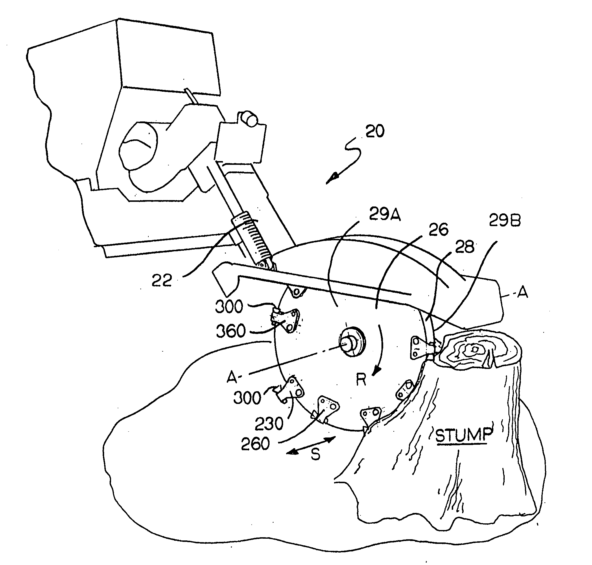
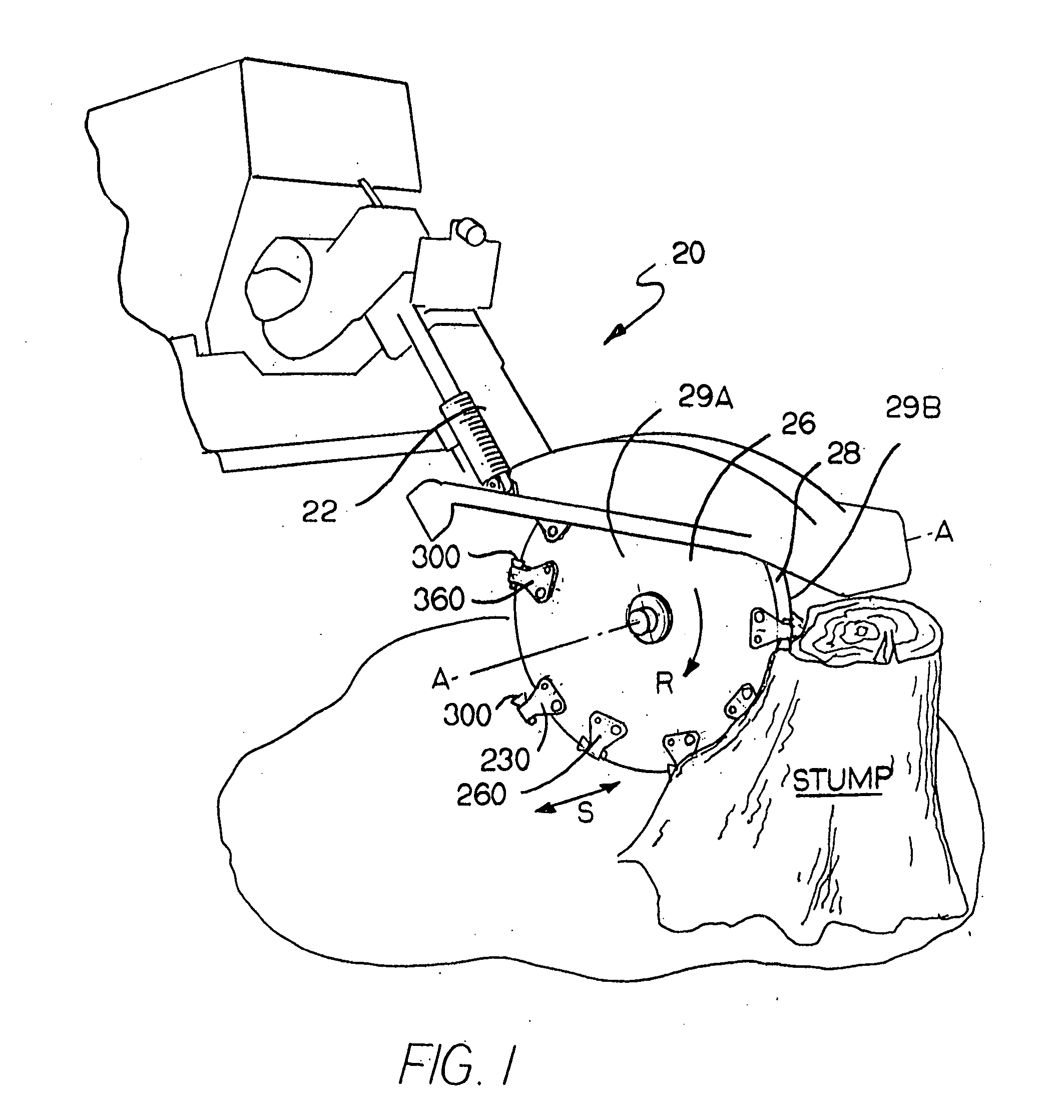
[0045]Referring to the drawings, in FIG. 1 there is illustrated a stump cutter assembly (generally designated as 20) that is in engagement with a stump (designated as “STUMP”). Stump cutter assembly 20 uses the stump cutter tooth assemblies (e.g., stump cutter teeth and pockets) shown and described in this patent application. This particular stump cutter assembly (or stump cutter machine) is a Vermeer SC352 stump cutter made and sold by Vermeer Mfg. Co., 1210 Vermeer Road East, Pella, Iowa 50219. However, there is no intention to limit or restrict the scope of the invention to any specific type or kind of stump cutter assembly.

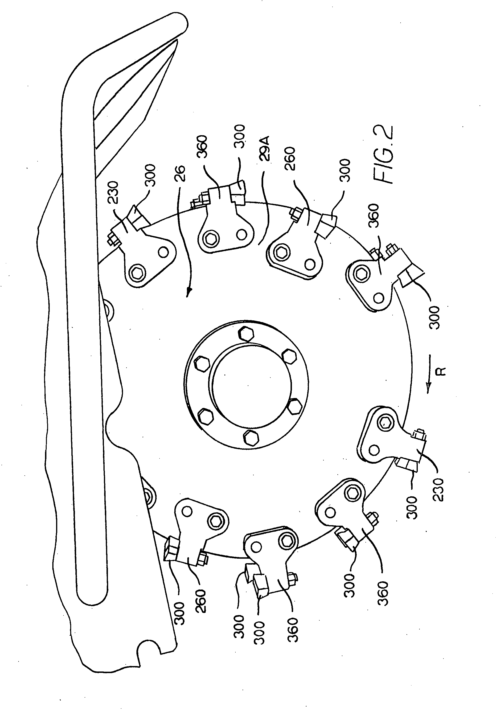
[0046]Still referring to FIG. 1, stump cutter assembly 20 has an arm (or frame) 22 with a distal end and to which is operatively rotatably attached a driven cutting wheel 26 about a first axis A-A. Driven cutting wheel 26 has a circumferential (or peripheral) edge 28 and a radial outer portion that has its radial outer termination at the circumferential edge. ...


PUM


Abstract

A stump cutter tooth held by a pocket member, which has first and second edge, and the pocket member being operatively attached to a driven wheel, which has opposite first and second side surfaces. The stump cutter tooth includes an elongate tooth body that has an axial forward end. A first hard region is at the axial forward end of the tooth body and defines at least one distinct cutting edge that has an orientation to engage the stump during operation. A second hard region is at the axial forward end of the tooth body and is distinct from the first hard region. The second hard region provides protection to at least a portion of the pocket member.

Description

REFERENCE TO EARLIER RELATED PATENT APPLICATION[0001]This patent application is based upon pending U.S. Provisional Patent Application Ser. No. 60 / 856,173 filed on Nov. 2, 2006 by Ritchey et al. for an INDEXABLE STUMP CUTTER, and applicants claim priority on said provisional patent application (i.e., U.S. Provisional Patent Application Ser. No. 60 / 856,173 filed on Nov. 2, 2006 by Ritchey et al. for an INDEXABLE STUMP CUTTER), which is incorporated herein by reference in its entirety.BACKGROUND OF THE INVENTION[0002]The present invention pertains to a cutter tooth that has a hard insert at the axial forward end wherein the cutter tooth is useful to impinge and / or disintegrate a piece of material such as, for example, wood or earth strata. More specifically, the invention pertains to such a cutter tooth (such as, for example, an indexable stump cutter tooth), that when used in a stump cutter machine allows the stump cutter machine to experience an increase in operational efficiency (i...

Claims


Application Information

Patent Timeline
IPC IPC(8): A01G23/06
CPCA01G23/067
Inventor KAPPEL, GARY W.LYNG, THOMAS R.RITCHEY, CARY D.ROWLETT, DON C.
Owner KENNAMETAL INC
Why Eureka
Try Eureka