Heat Sink Structure for High Power LED Lamp

a technology of led lamps and heat sinks, applied in cooling/ventilation/heating modifications, lighting and heating apparatus, etc., to achieve good convection

Inactive Publication Date: 2008-06-26
CHEN TE CHUNG +1
View PDF7 Cites 31 Cited by
  • Summary
  • Abstract
  • Description
  • Claims
  • Application Information

AI Technical Summary

Benefits of technology

[0009]The heat sink comprises a plurality of heat sink fins made of highly heat-conductive material, the plurality of heat sink fins are arranged radially to form a porous center structure with no occluding junction, thereby implementing a heat sink structure which can provide omnidirectional heat dissipating capability and good convection capability to let hot air to rise naturally for high power LED lamps.

Problems solved by technology

However, due to various concerns such as noise, life span, energy-saving, and size, etc., it is not a welcome option to include fan(s) inside high power LED lamps at present; but fanless heat sink devices could have heat sink fins linked in such configurations (or arranged in such angles) that inappropriately block the natural convection direction of hot air.

Method used


Image

  • Heat Sink Structure for High Power LED Lamp
  • Heat Sink Structure for High Power LED Lamp
  • Heat Sink Structure for High Power LED Lamp

Examples


Embodiment Construction

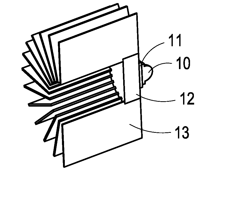
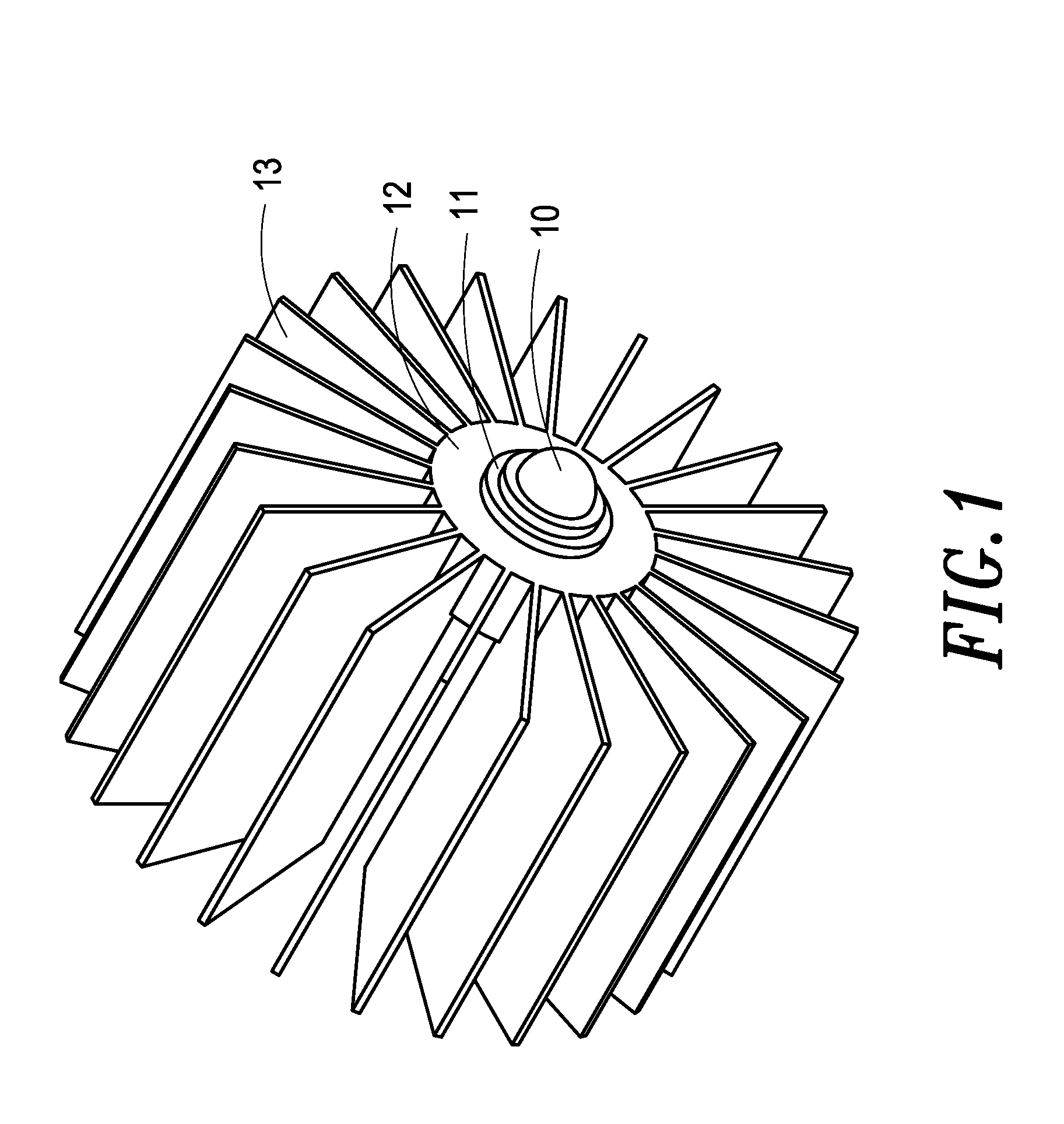
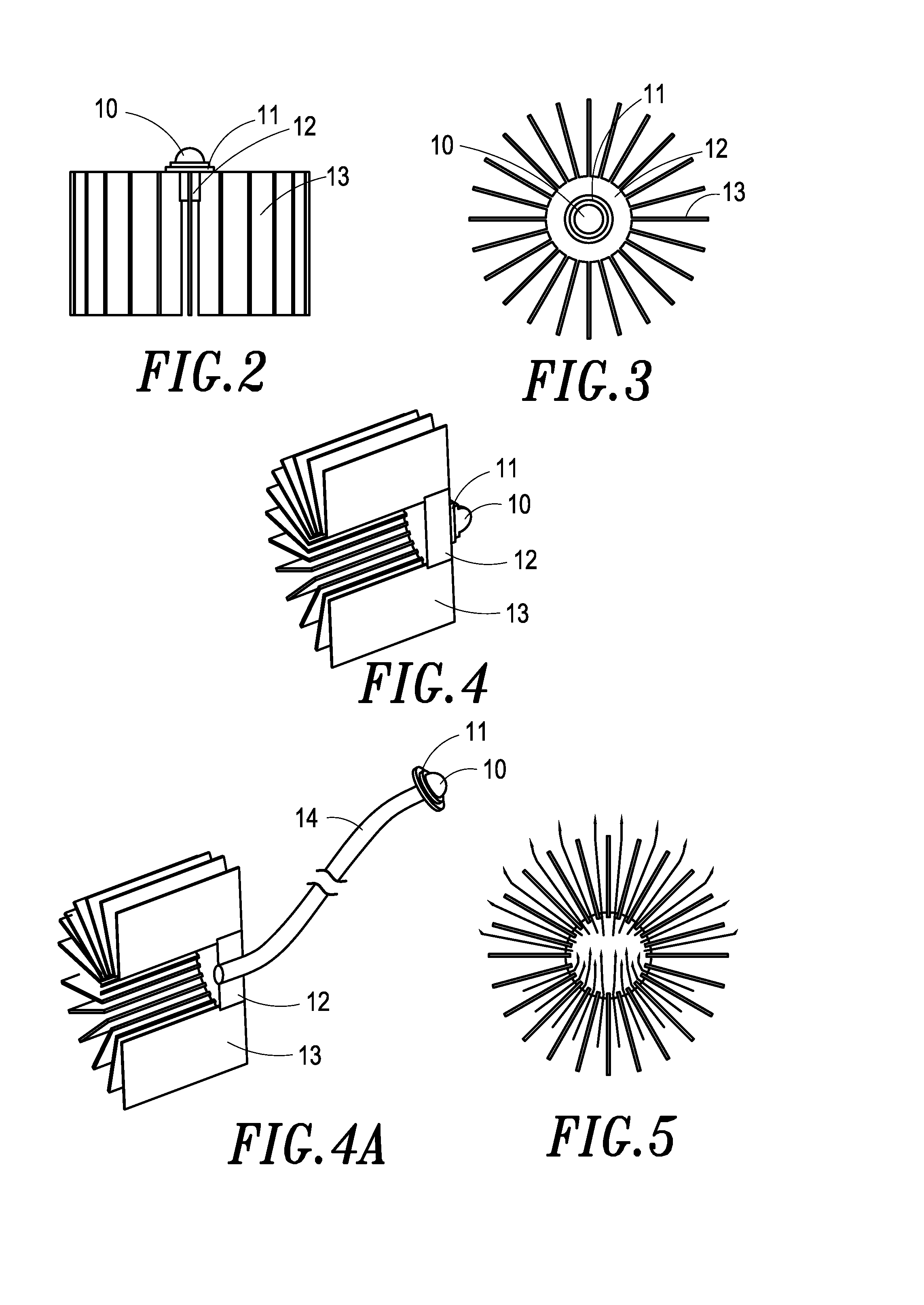
[0021]Please refer to FIG. 1, FIG. 2, and FIG. 4 for a heat sink structure for high power LED lamp disclosed in the present invention, the heat sink structure mainly comprises an LED lamp 10, a heat conducting lamp holder 11, a heat conductor 12 and a heat sink 13, wherein the heat conducting lamp holder 11 is made of highly heat-conductive material such as copper, aluminum, zinc, or ceramic, to provide a smooth surface for heat conductive glue or solder (made of tin) to glue the smooth surface and a heat conducting base of the LED lamp 10 together; moreover, the heat conductor 12 is made of highly heat-conductive material, it is mainly used for linking the heat conducting lamp holder 11 and the heat sink 13; the heat sink 13 comprises a plurality of heat sink fins made of highly heat-conductive material and arranged radially, the heat sink fins of the heat sink 13 forms a porous center structure with no occluding junction; furthermore, please refer to FIG. 4A, the heat conductor 12...


PUM


Abstract

A heat sink structure for high power LED lamp includes a heat conducting lamp holder, a heat conductor and a heat sink. The heat conducting lamp holder is made of highly heat-conductive material to provide a smooth surface for firmly holding an LED lamp. The heat conductor is made of highly heat-conductive material for linking the heat conducting lamp holder and the heat sink. The heat sink includes a plurality of heat sink fins made of highly heat-conductive material. The plurality of heat sink fins are arranged radially to form a porous center structure with no occluding junction, thereby implementing a heat sink structure which can provide omnidirectional heat dissipating capability and good convection capability to let hot air to rise naturally for high power LED lamps.

Description

BACKGROUND OF THE INVENTION[0001]1. Field of the Invention[0002]The present invention relates to a heat sink structure for high power LED lamp, and, more particularly, to a heat sink structure having a plurality of heat sink fins arranged radially to form a porous center structure with no occluding junction, thereby implementing a heat sink structure which can provide a omnidirectional heat dissipating capability and a good convection capability to let hot air to rise naturally for high power LED lamps.[0003]2. Description Of The Prior Art[0004]Recently high power LEDs are more and more important in applications such as illumination, traffic lights, ambience lights and backlight modules, etc. due to energy-saving considerations. However, high power LEDs tend to generate more heat, therefore highly efficient heat sink devices are needed to exploit the high brightness and to prolong the life spans of high power LEDs.[0005]Conventional heat sink device comprises heat sink fins made of ...

Claims


Application Information

Patent Timeline
Patent Type & Authority Applications(United States)
IPC IPC(8): H05K7/20
CPCF21K9/00F21V29/773F21V29/767F21V29/006F21Y2115/10
Inventor CHEN, TE-CHUNG
Owner CHEN TE CHUNG
Why Eureka
Try Eureka