RF power transistor with large periphery metal-insulator-silicon shunt capacitor

a technology of metal-insulator-silicon shunt capacitor and power transistor, which is applied in the direction of semiconductor devices, semiconductor/solid-state device details, electrical apparatus, etc., can solve the problems of reducing the power, gain and efficiency and the performance of rf power transistor is particularly noticeable, and the traditional integrated shunt capacitor has poor rf performan

a technology of metal-insulator-silicon shunt capacitor and power transistor, which is applied in the direction of semiconductor devices, semiconductor/solid-state device details, electrical apparatus, etc., can solve the problems of reducing the power, gain and efficiency and the performance of rf power transistor is particularly noticeable, and the traditional integrated shunt capacitor has poor rf performan

US20080149981A1Active Publication Date: 2008-06-26NXP USA INC

Image

  • RF power transistor with large periphery metal-insulator-silicon shunt capacitor
  • RF power transistor with large periphery metal-insulator-silicon shunt capacitor
  • RF power transistor with large periphery metal-insulator-silicon shunt capacitor

Examples


Embodiment Construction

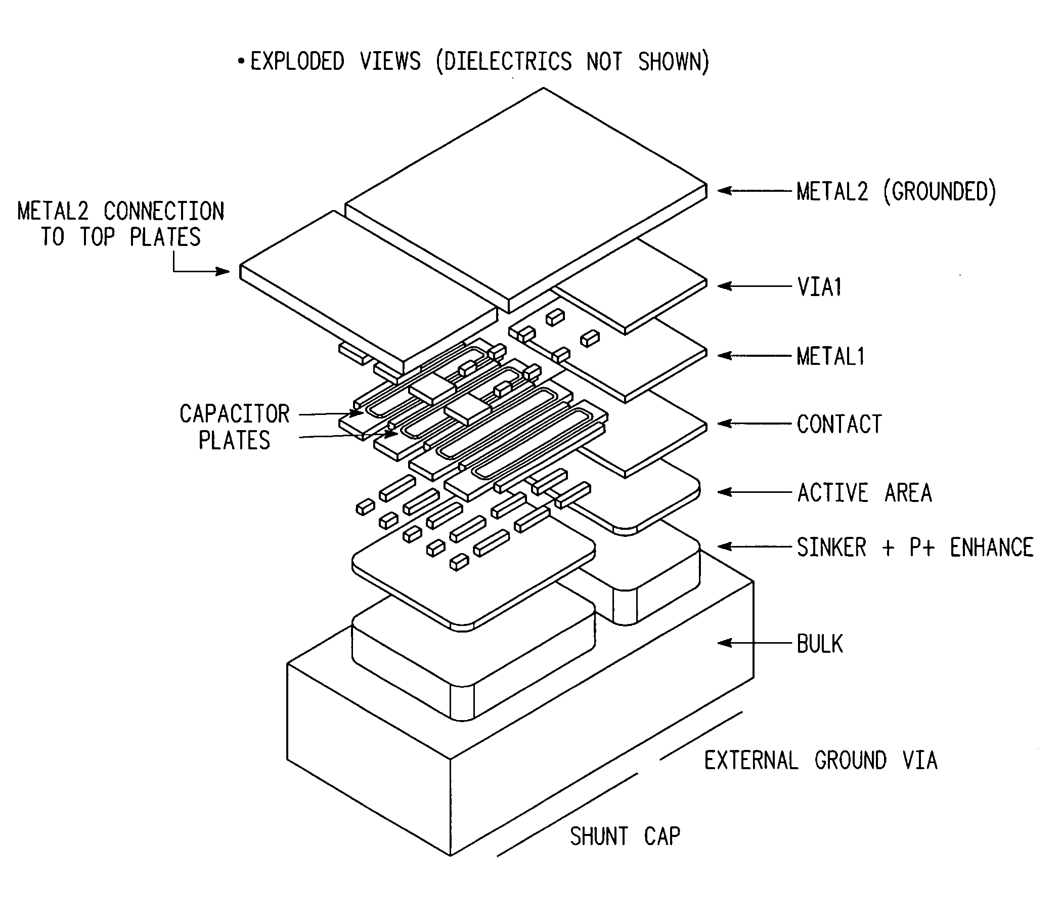
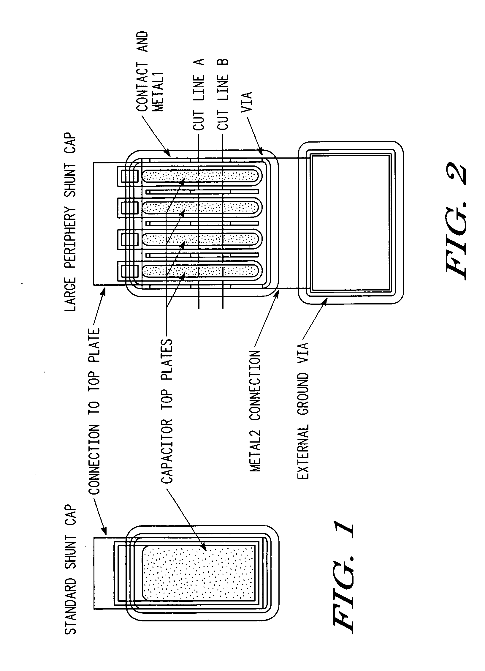
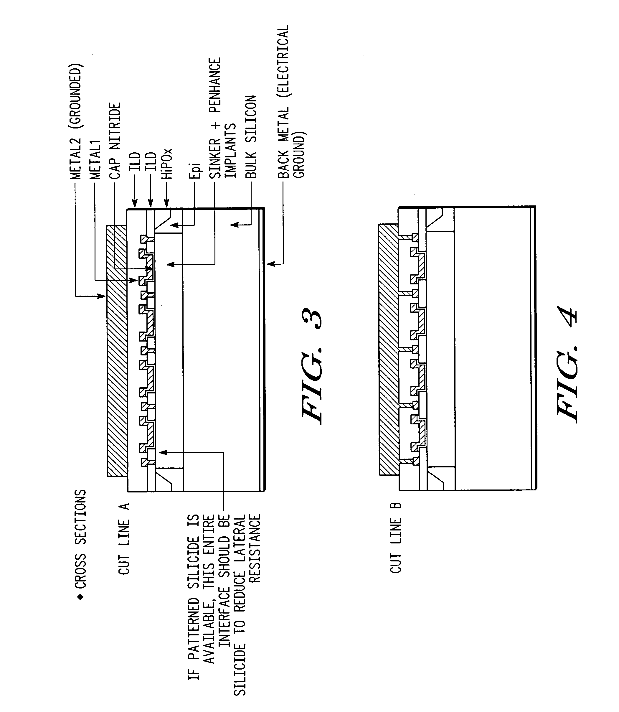
[0021]The embodiments according to the present disclosure provide a novel layout for metal-insulator-semiconductor (MIS) shunt capacitors, wherein the MIS shunt capacitor layout improves the quality factor (denoted “Q”) of the MIS shunt capacitor over conventional rectangular MIS shunt capacitor layouts. In other words, the MIS shunt capacitor according to the embodiments of the present disclosure advantageously reduces the undesirable resistive losses of shunt capacitors in integrated circuits with high resistivity substrates.

[0022]According to one embodiment of the present disclosure, a metal-insulator-semiconductor (MIS) shunt capacitor comprises an MIS output matching shunt capacitor having a large periphery and having portions disposed proximate metal that is coupled to ground through an external ground via. Such a configuration facilitates charging of the capacitor bottom plate laterally with a lateral current flow, in addition to charging with a vertical current flow.

[0023]By...


PUM


Abstract

An integrated MIS capacitor structure comprises a high quality factor shunt capacitor. The integrated MIS capacitor is configured with a large periphery and an external ground via to mitigate resistive losses in the bottom plate of the MIS shunt capacitor.

Description

CROSS-REFERENCE TO CO-PENDING APPLICATIONS[0001]This application claims priority to provisional patent application Ser. No. 60 / 871,114 entitled “RF POWER TRANSISTOR WITH LARGE PERIPHERY METAL-INSULATOR-SILICON SHUNT CAPACITOR,” filed on Dec. 20, 2006, and assigned to the assignee of the present application.BACKGROUND[0002]1. Field[0003]This disclosure relates generally to RF devices, and more specifically, to an RF power transistor device with a large periphery Metal-Insulator-Silicon shunt capacitor and method thereof.[0004]2. Related Art[0005]RF transistor designs have traditionally included an integrated shunt capacitor design; however, the traditional integrated shunt capacitor has poor RF performance. In other words, such a traditional integrated shunt capacitor design degrades the RF power transistor's power, gain and efficiency. Such degradation in RF power transistor performance is especially noticeable in high power RF power transistor plastic package designs.[0006]In a kno...

Claims


Application Information

Patent Timeline
26 Jun 2008
Publication
US20080149981A1
IPC
H01L29/94
CPC
H01L23/642; H01L23/66; H01L29/94; H01L2223/6644; H01L2924/0002; H01L2924/3011; H01L2924/00
Inventors
LAMEY, DANIEL J.; REN, XIAOWEI