
System and Method for Creating a Geothermal Roadway Utility with Alternative Energy Pumping System

Active Publication Date: 2008-06-26
TAMIRAS PER PTE LTD LLC
View PDF38 Cites 53 Cited by
  • Summary
  • Abstract
  • Description
  • Claims
  • Application Information

AI Technical Summary

Benefits of technology

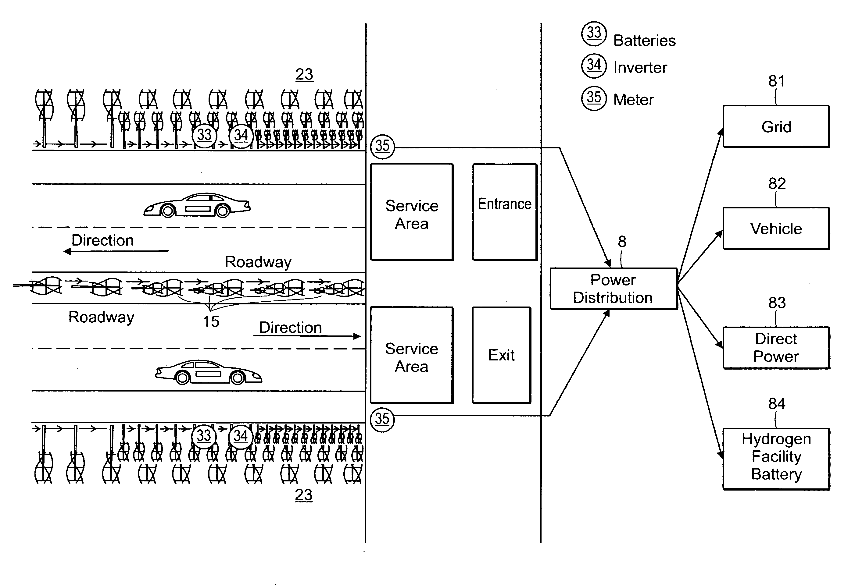
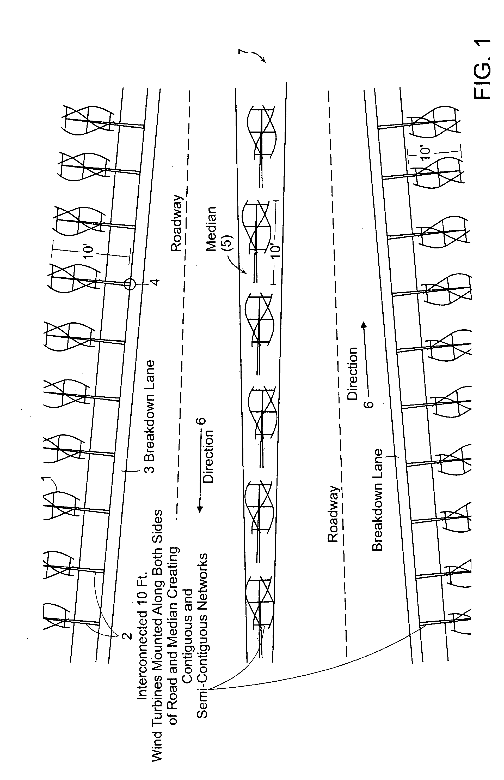
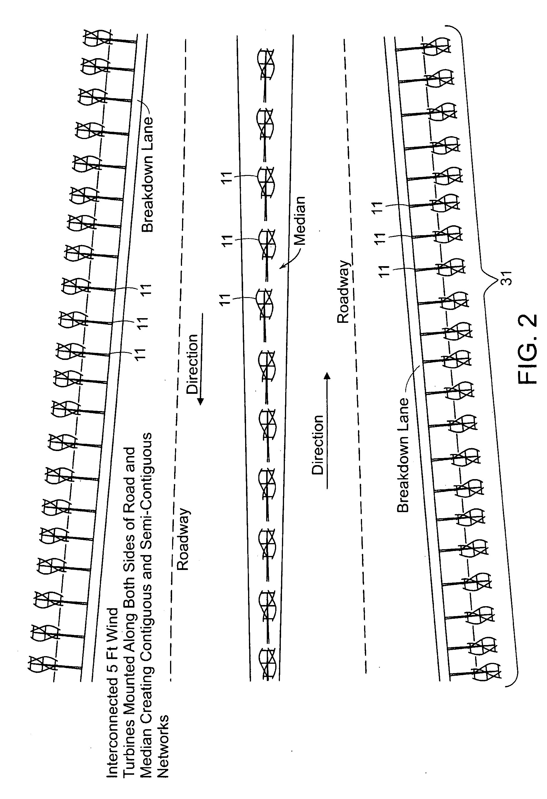
[0009]One embodiment of the present invention is a roadway system for energy generation and distribution. This system allows a geothermal infrastructure to be tied into the roadway system electricity grid. The geothermal infrastructure may include energy exchangers that are electrically connected to the roadway system electricity grid. By connecting the energy exchangers electrically to the roadway system electricity grid, the energy exchangers may be powered by solar and/or wind generating devices. In one embodiment of the invention, a roadway system for energy generation and distribution comprises a plurality of energy harnessing devices (e.g., solar and wind generating devices). The roadway system electricity grid is configured for mass distribution of electricity. The energy exchangers are configured to electrically connect to the roadway system electricity grid. Each of substantially a

Problems solved by technology

The by-products produced by combustion systems contain harmful emissions.
These emissions degrade air quality and negatively impact individuals' health and contribute to environmental problems (e.g., acid rain and the greenhouse effect).
Existing conventional uses of geothermal energy systems have limitations in distribution and deployment.
The costs may be insurmountable for many families, businesses, and municipalities.
Some homes or businesses are precluded from digging the geothermal underground network system due to zoning, topographic, space or geologic factors that appear on potential geothermal system user's land sites.

Method used


Image

  • System and Method for Creating a Geothermal Roadway Utility with Alternative Energy Pumping System
  • System and Method for Creating a Geothermal Roadway Utility with Alternative Energy Pumping System
  • System and Method for Creating a Geothermal Roadway Utility with Alternative Energy Pumping System

Examples


Embodiment Construction

[0052]The present invention provides a roadway system that can provide the basis for a national or global clean or renewable energy infrastructure. A geothermal heating and cooling system can be implemented along short or long stretches of riparian body for the purposes of creating power to meet both small and large power demands. The power generated by the geothermal system can be used to power both heating and cooling of homes, businesses or systems without connecting to existing grid systems.

[0053]A “road” (hereinafter also “roadway”) as used herein, is an identifiable route or path between two or more places on which vehicles can drive or otherwise use to move from one place to another. A road is typically smoothed, paved, or otherwise prepared to allow easy travel by the vehicles. Also, typically, a road may include one or more lanes, one or more breakdown lanes, one or more medians or center dividers, and one or more guardrails. For example, a road may be: a highway; turnpike;...


PUM


Abstract

A roadway system and method for energy generation and distribution are presented. This system allows a geothermal infrastructure to be tied into the roadway system electricity grid. The geothermal infrastructure may include energy exchangers that are electrically connected to the roadway system electricity grid. By connecting the energy exchangers electrically to the roadway system electricity grid, the energy exchangers may be powered by solar and / or wind generating devices. In one embodiment of the invention, a roadway system for energy generation and distribution comprises a plurality of energy harnessing devices (e.g., solar and / or wind generating devices). The roadway system electricity grid is configured for mass distribution of electricity. The energy exchangers are configured to electrically connect to the roadway system electricity grid. Each of substantially all of the energy harnessing devices, is electrically connected to the roadway system electricity grid and positioned on part of one of the roads.

Description

RELATED APPLICATION[0001]This application is a continuation in part application of U.S. application Ser. No. 11 / 765,812, entitled “SYSTEM AND METHOD FOR CREATING AN OPEN LOOP WITH OPTIONAL CLOSED LOOP RIPARIAN GEOTHERMAL INFRASTRUCTURE”, filed on Jun. 20, 2007, which is a continuation in part application of U.S. application Ser. No. 11 / 747,061, entitled “SYSTEM AND METHOD FOR CREATING A CLOSED-LOOP RIPARIAN GEOTHERMAL INFRASTRUCTURE”, filed on May 10, 2007, which is a continuation in part application of U.S. application Ser. No. 11 / 742,339, entitled “SYSTEM AND METHOD FOR CREATING A GEOTHERMAL ROADWAY UTILITY”, filed on Apr. 30, 2007, which is a continuation in part application of U.S. application Ser. No. 11 / 645,109, entitled “SYSTEM AND METHOD FOR CREATING A NETWORKED INFRASTRUCTURE DISTRIBUTION PLATFORM OF FIXED AND MOBILE SOLAR AND WIND GATHERING DEVICES”, filed on Dec. 22, 2006. The entire teachings of the above applications are incorporated herein by reference.BACKGROUND OF TH...

Claims


Application Information

Patent Timeline
IPC IPC(8): F03G7/08
CPCF03D9/002H02S99/00F03G7/08F05B2220/61F05B2240/212F05B2240/9113F05B2240/941F05B2250/25F05B2250/82F24J3/081Y02B10/30Y02B10/70Y02E10/12Y02E10/465Y02E10/725Y02E70/10Y02E10/728F03D9/007F03D3/02F03G7/04F03D9/11F03D9/25F03D9/255F24T10/10H02S10/12Y02B10/10Y02E10/10Y02E10/50Y02E10/74Y02E60/36
Inventor FEIN, GENE S.MERRITT, EDWARD
Owner TAMIRAS PER PTE LTD LLC
Learn More