Safety cabinet

a biohazard and safety technology, applied in the direction of chimneys, isotope separation, combinatorial devices, etc., can solve the problems of limited hand movement range in the working space, difficult treatment for workers of low body height, etc., and achieve the effect of convenient us

Active Publication Date: 2008-06-26
HITACHI IND EQUIP SYST CO LTD
View PDF7 Cites 20 Cited by
  • Summary
  • Abstract
  • Description
  • Claims
  • Application Information

AI Technical Summary

Benefits of technology

[0006]An object of the present invention is to provide a safety cabinet easily usable for any worker of various height.

Problems solved by technology

In the prior art, there is a problem of that a movable range of a hand in the working space is limited by a fixed size of the front opening when the microorganism or causal organism is treated.
Further, there is a weak point of that the treatment is difficult for the worker of low body height when the size of the front opening of the safety cabinet is 250-300 mm greater than normal size of 200 mm.

Method used


Image

  • Safety cabinet
  • Safety cabinet
  • Safety cabinet

Examples


embodiment 1

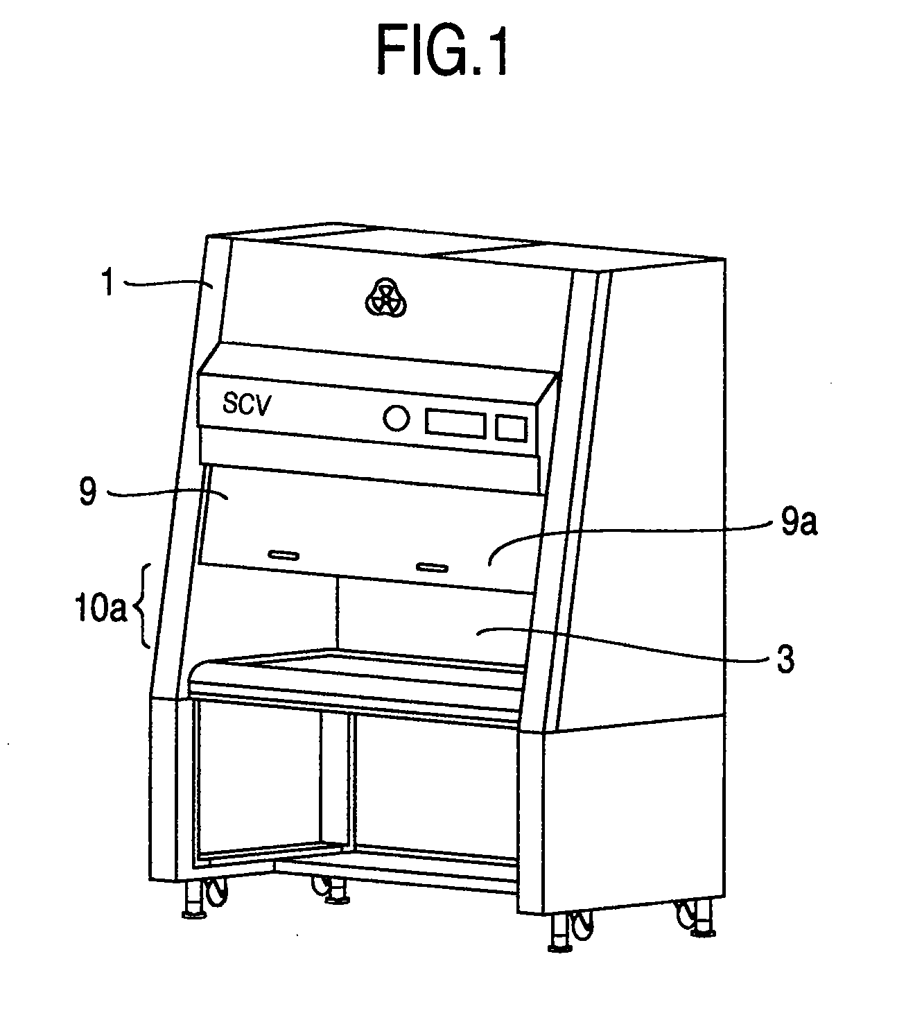
[0027]FIG. 1 is a schematic oblique projection view showing a safety cabinet as a first embodiment of the invention.

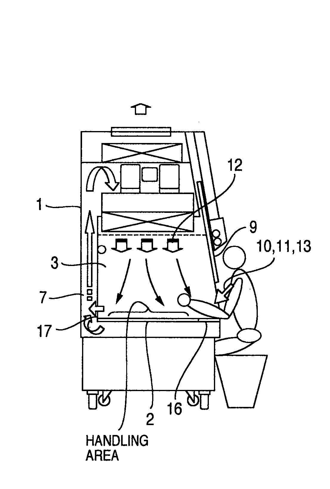
[0028]A worker extends his or her arm into a safety cabinet 1 through a front opening 10, and looks into a working space 3 through a front surface shutter 9 to treat bacteria or virus.

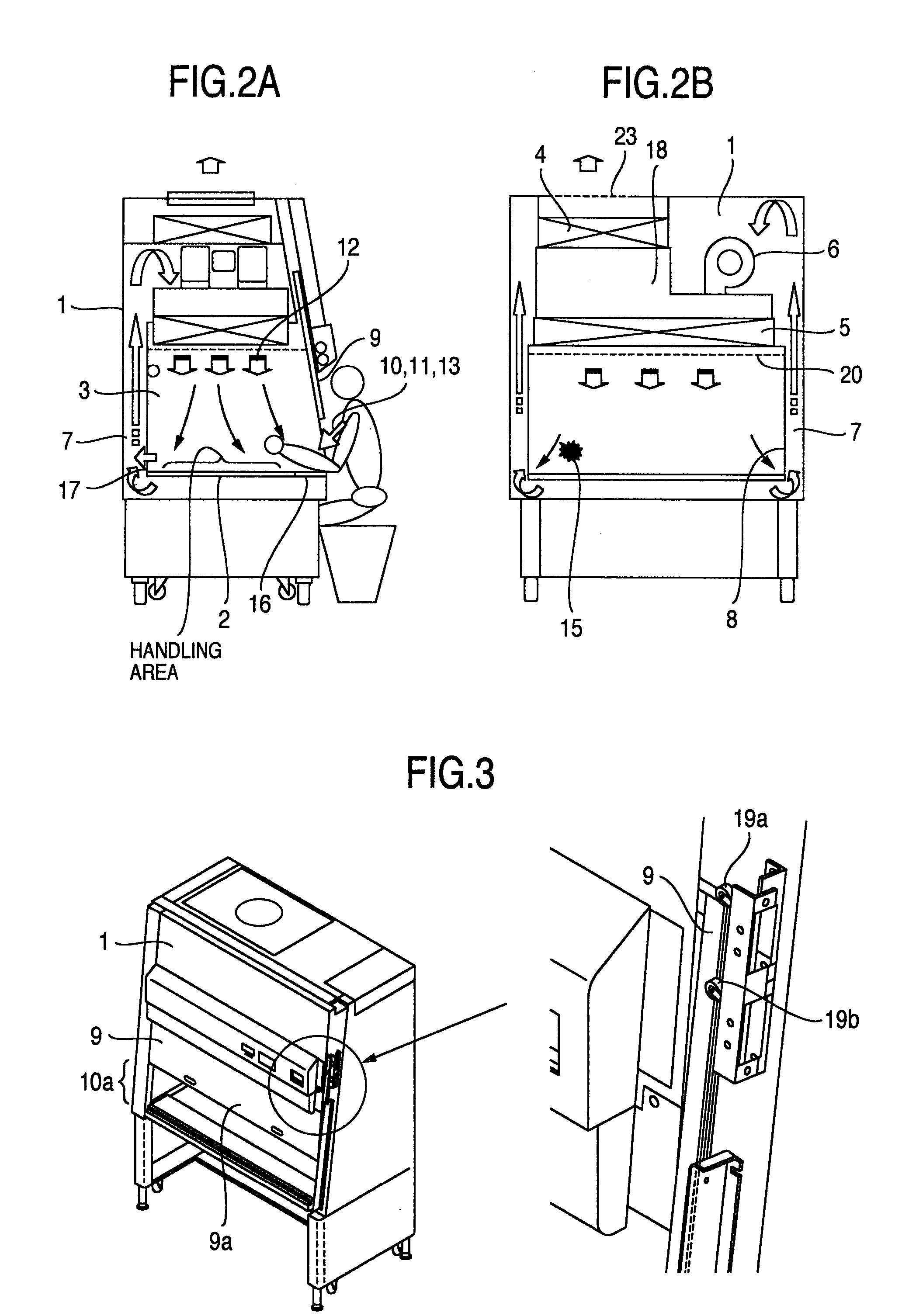
[0029]FIG. 2A is a partially cross sectional view showing the safety cabinet as the first embodiment of the invention. FIG. 2B is another partially cross sectional view showing the safety cabinet as the first embodiment of the invention.

[0030]A clean air is supplied from a HEPA filter 5 into the working space 3 of the safety cabinet 1 through a straightening vane 20.

[0031]An air 13 taken through the front opening into the safety cabinet flows to a blower 6 through a circulating path extending under a working table 2 and a back side of the working space 3. The air taken into the blower 6 is pressurized in a pressure chamber 18. The pressure chamber 18 communicates with a HEPA filter 4 for ...

embodiment 2

[0044]FIG. 4A is a partially cross sectional view showing the safety cabinet as a second embodiment of the invention, and FIG. 4B is another partially cross sectional view showing the safety cabinet as the second embodiment of the invention while FIG. 1 shows the schematic view of the safety cabinet 1.

[0045]A damper 25 is arranged in a pressure chamber 18. The air output from the blower 6 is pressurized in the pressure chamber 18. The HEPA filter 4 for discharging the air and the HEPA filter 5 for supplying the air communicate with the pressure chamber 18 so that the air is distributed between a exhaust port 23 and the working space 3. The damper 25 is arranged in the pressure chamber 18 to adjust the air toward the HEPA filter 4 for discharging the air. When the damper 25 is opened, a flow rate toward the HEPA filter 4 is increased, and when the damper 25 is closed a flow rate toward the HEPA filter 5 for supplying the air is increased. In accordance with the size 10a of the front ...

embodiment 3

[0051]FIG. 5A is a partially cross sectional view showing the safety cabinet as a second embodiment of the invention, and FIG. 5B is another partially cross sectional view showing the safety cabinet as the second embodiment of the invention while FIG. 1 shows the schematic view of the safety cabinet 1.

[0052]An intake slit damper 21 to be driven by an actuator for changing an opening area of the front intake slit 16 is arranged. By opening the intake slit damper 21, a flow rate of the air taken into the front opening 10=a flow rate of the air discharged from the exhaust port 23 is increased, and by closing the intake slit damper 21, the flow rate of the air taken into the front opening 10 is decreased. In such structure, the flow rate of the air taken into the front opening 10 is controlled in accordance with ON / OFF signal of the limit switch 19 for detecting the position of the front surface shutter 9.

[0053]Table 4 shows an example of control in the third embodiment.

TABLE 4Front ope...


PUM

PropertyMeasurementUnit
sizeaaaaaaaaaa
sizeaaaaaaaaaa
sizeaaaaaaaaaa

Abstract

A safety cabinet adaptable for a variation in body height of a worker using the safety cabinet, that is, a safety cabinet which prevents various bacteria from proceeding from the outside of the safety cabinet into a working space of the safety cabinet and prevents bacteria or virus from proceeding from the working space to the outside of the safety cabinet irrespective of a change in opening area of a front opening, is provided.
A flow velocity of a clean air supplied into the working space and a flow velocity of the air flowing through the front opening are set at respective velocities predetermined to keep a physical isolation for preventing the contamination in accordance with a size of the front opening.
Further, in the safety cabinet, the size of the front opening communicating with the working space under the front surface shutter is adjustable between 200 mm and 300 m.

Description

INCORPORATION BY REFERENCE[0001]The present application claims priority from Japanese application JP2006-342072 filed on Dec. 20, 2006, the content of which is hereby incorporated by reference into this application.BACKGROUND OF THE INVENTION[0002]The present invention relates to a safety cabinet for biohazard, that is, a clean worktable enabling a hazard to be prevented from being caused by a treatment of microorganism or causal organism for genetic manipulation in medical or pharmaceutical field or an investigation of the causal organism for an investigation of infection disease.[0003]In the prior art, a safety cabinet is used as a primary barrier for physically isolating a human body or an environment from the microorganism or causal organism to be treated. In a prior art safety cabinet, an opening area of a front opening is fixed as disclosed by JP-A-62-132550, and a flow rate through the front opening is measured by a flow rate sensor so that a blower is controlled to keep the ...

Claims


Application Information

Patent Timeline
Patent Type & Authority Applications(United States)
IPC IPC(8): A47B81/00B01L1/00F24F7/06
CPCA47B9/00A47B81/00A47B2200/0019Y10S55/18F24F3/1607F24F7/007B08B15/023B25H1/20F24F3/163
Inventor ONO, KEIICHI
Owner HITACHI IND EQUIP SYST CO LTD
Why Eureka
Try Eureka