Remote control system for medical apparatus

Inactive Publication Date: 2008-06-26
CARL ZEISS SURGICAL
View PDF9 Cites 93 Cited by
  • Summary
  • Abstract
  • Description
  • Claims
  • Application Information

AI Technical Summary

Benefits of technology

[0024]The signal can be transmitted from the remote control operating unit to the device to be controlled by means of a radio network link. As mentioned above, the advantage of a radio link is networking of devices without disturbing cables.
[0025]In an advantageous development of the invention, the remote control operating unit recognizes when it does not have a charging contact to the charging station and the radio network link to the device is interrupted over a particular period of time. It then generates a signal, for example a light signal or a signal tone. If the remote control operating unit finds that there is no network link to the device, this can mean that the device is switched off. If there is additionally no charging contact to the charging station, the risk is that the device is stored with the remote control system without power supply and it has been forgotten to establ

Problems solved by technology

It is disadvantageous that, for example, Bluetooth is a network transmission and the network of remote control and device to be controlled must be continuously maintained even if no control commands are being exchanged at the time.
This results in relatively high power consumption of the remote control.
In many operating theatres, however, the power supply is centrally switched off if it is not used or the device to be controlled, for example a surgery microscope, is stored after its use in a storage room without power connection so that charging in the vicinity of the device is not

Method used


Image

  • Remote control system for medical apparatus
  • Remote control system for medical apparatus
  • Remote control system for medical apparatus

Examples


Embodiment Construction

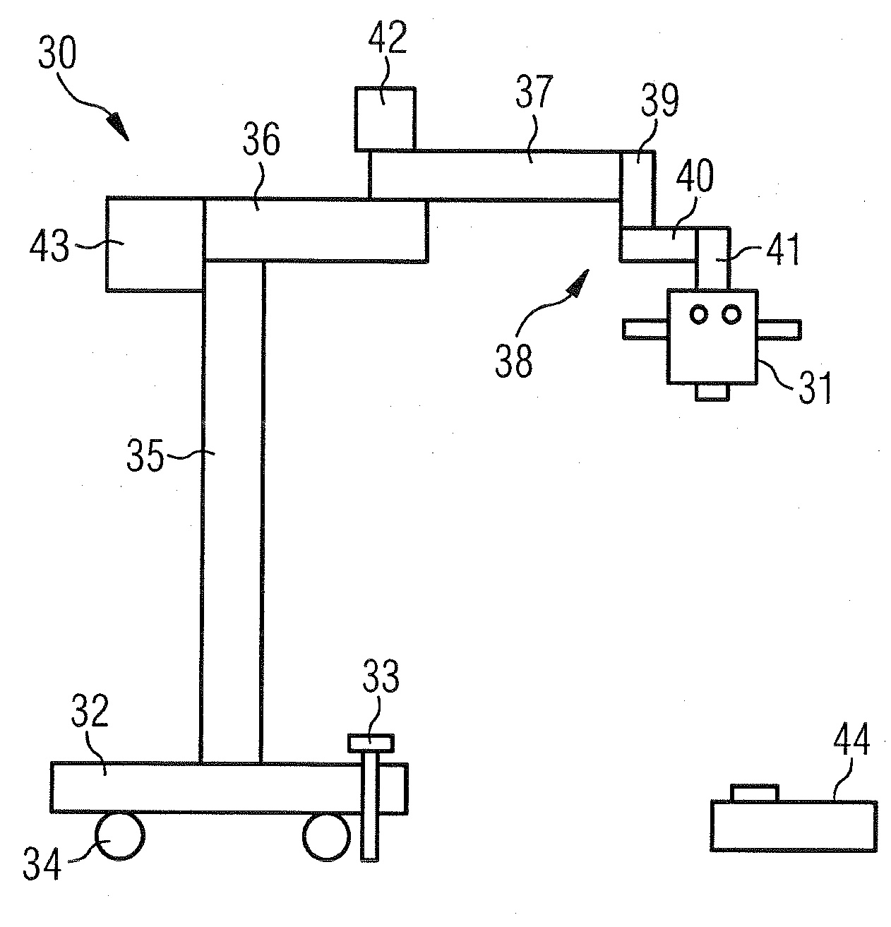
[0037]FIG. 1 diagrammatically shows a surgery microscope 31 with a stand 30 as an example of a medical device in which a remote control system according to the invention can be used. The stand 30 rests on a foot 32 at the underside of which rollers 34 are present which enable the stand 30 to be moved. To prevent an unwanted movement of the stand 30, the foot 32 also has a foot brake 33.

[0038]To remotely control the stand and / or the surgery microscope 31, there is a foot pedal console 44 as remote control operating unit which is connected to a control module (not shown) in the surgery microscope 31 via a radio network link.

[0039]The stand 30 comprises a height-adjustable stand column 35, a support arm 36, a spring arm 37 and a microscope suspension 38 which, in turn, comprises a connecting element 39, a swiveling arm 40 and a holding arm 41.

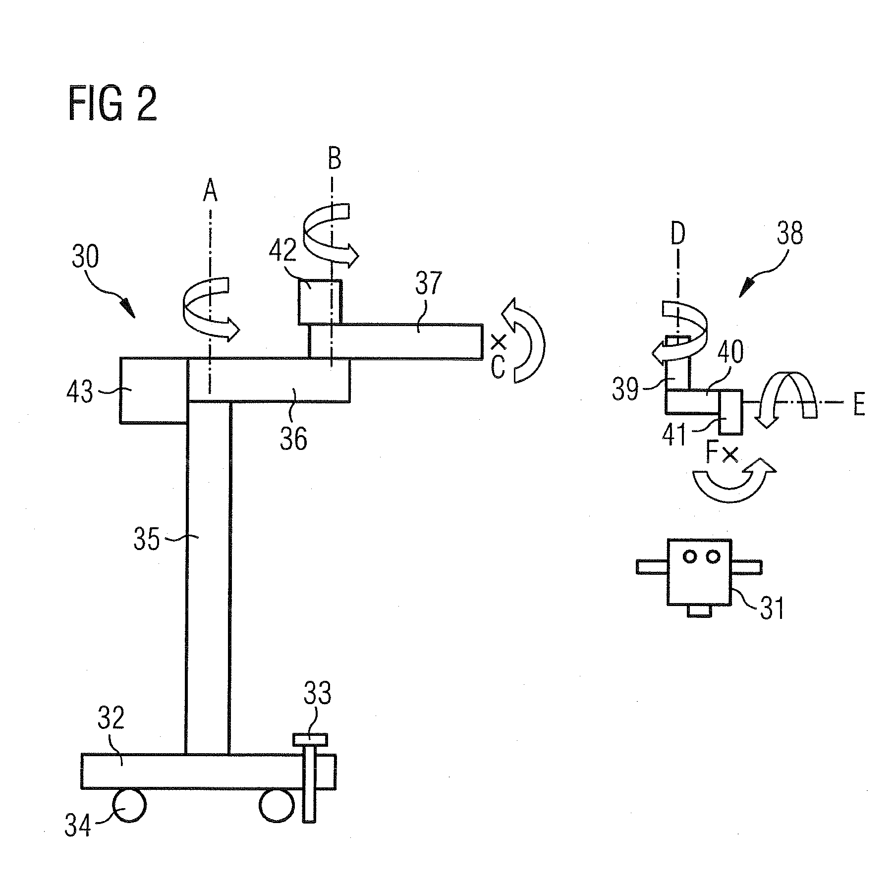
[0040]The degrees of freedom provided by the stand elements for positioning the surgery microscope 31 are shown in FIG. 2. The support arm 36 is ...


PUM


Abstract

A cableless remote control system (2) for a medical device is provided. The remote control system (2) comprises a first battery (16), a second battery (18), a control module (10) for attaching or for installing in the medical device (8), at least one remote control operating unit (6) and a charging station (4). The first battery (16) is arranged in the remote control unit (6), the second battery is allocated to the charging unit (4).

Description

BACKGROUND OF THE INVENTION[0001]1. Field of the Invention[0002]The invention relates to a cableless remote control system for medical devices and a method for charging a battery of a remote control.[0003]2. Description of the Related Art[0004]In cableless remote controls for surgical devices or optical observation devices, particularly surgery microscopes, the necessary control signals are transmitted wirelessly instead of via a cable. For this purpose, a network link, for example Bluetooth, is used. For a medical remote control, Bluetooth is a suitable transmission technology because the frequency used is permitted throughout the world and the transmission technology is relatively secure against interference. To build up the voltage necessary for the network link, an internal power supply, i.e. a power source in the form of a battery is used.[0005]DE 102 35 956 A1 discloses an arrangement for the wireless transmission of actuating signals to a number of medical devices. In the med...

Claims


Application Information

Patent Timeline
IPC IPC(8): H04Q9/00
CPCA61B1/00016A61B1/00055A61B19/5223A61B2017/00017A61B2017/00119A61B2017/00212A61B2017/00221A61B2017/00734A61B2017/00973A61B2019/2269A61B2560/0456A61F9/00745H02J7/0054H02J7/025A61B1/00034A61B19/52A61B90/36A61B34/74A61B90/20H02J7/342H02J7/0044H02J50/10H02J2310/23
Inventor QUENDT, DIETER
Owner CARL ZEISS SURGICAL
Why Eureka
Try Eureka