Network path control system, path control device, and path control method

a network and control system technology, applied in the field of network path control technology, can solve the problems of increasing convergence time, affecting the accuracy of path control,

Active Publication Date: 2008-06-26
NEC CORP
View PDF21 Cites 184 Cited by
  • Summary
  • Abstract
  • Description
  • Claims
  • Application Information

AI Technical Summary

Benefits of technology

[0012]According to the present invention, when the path control device determines a path of the network, it is possible to prevent the path control device from being influenced by the delay of the topology information from a communication node. Further, a path can be calculated based on the topology information to which an actual network state is refle

Problems solved by technology

It can be found from the graph of the drawing that as the number of the nodes of the network increases as well as the number of hops of the controller and a transfer path increase, the update of topology information is more delayed with a result that a convergence time increases.
However, the above network system has the following problems.
As presumed from FIG. 13 of Japanese Patent Application Laid-Open No. 2006-135975, a first problem resides in that it takes a time until the topology information held by the path control device are matched to the information recognized by a communication node as to actual network state depending on the size of a network and the disposition of the path control device.
This is because a delay occurs according to the dis

Method used


Image

  • Network path control system, path control device, and path control method
  • Network path control system, path control device, and path control method
  • Network path control system, path control device, and path control method

Examples


first embodiment

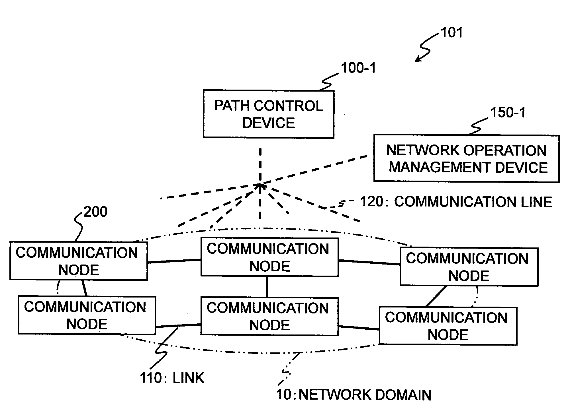
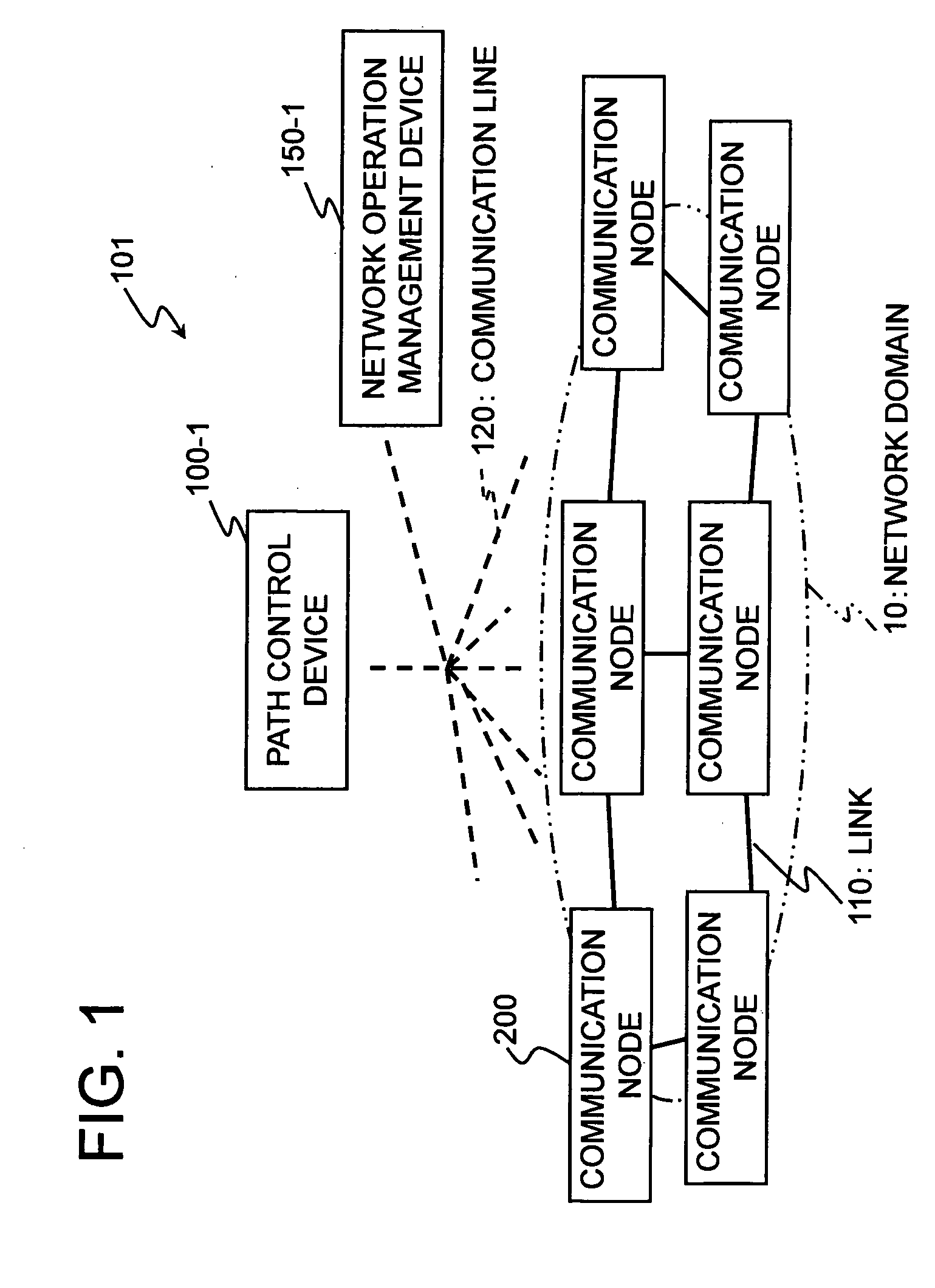
[0024]FIG. 1 shows a system arrangement of the present invention. A system 101 of the embodiment includes a path control device 100-1, a network operation management device 150-1, and a network domain 10. The system 101 is arranged as a single domain network. The domain means a set of one or a plurality of communication nodes. Exemplified as the domain is, an “area” defined by OSPF (Open Shortest Path First) as a kind of routing protocol, AS (Autonomous System) defined by BGP (Boarder Gateway Protocol), and the like.

[0025]The network domain 10 includes a plurality of communication nodes 200 connected by links 110. The network operation management device 150-1 manages the path of the network domain 10 and the arrangement of the network. In the system 101, all the communication nodes 200, the path control device 100-1 and the network operation management device 150-1 can exchange control management information such as topology information, path setup information and the like through a...

second embodiment

[0065]Accordingly, the second embodiment is unlike to be affected by the delay of the update information of a network even in a large-scale network bridged to multi-domains. Therefore, the path control device 100-2 can calculate reliable path information at all times.

[0066]Note that, in the above respective embodiments, although the path control device 100 is arranged as a device different from the communication nodes 200 for the purpose of convenience, the embodiments of the present invention need not be restricted to the above arrangements. As another arrangement, the function of the path control device may be mounted on, for example, one of the communication nodes belonging to a network domain and the communication node may be used as a representative path control device.

[0067]The present invention can be applied to an application for solving a path in a large-size path switching network. Further, the present invention is preferable to various types of systems in which a delay of...


PUM


Abstract

A path control device includes a TE database and a local database for storing topology information showing states of use of links in a network, a topology information collection unit collecting the topology information of the respective communication nodes therefrom and updating the TE database by the topology information, a path solution unit determining a path of the network referring to the local database, an internal update unit recognizing a link included in the determined path and updating a local database by information as to said link, and an update determination unit matching the topology information of both the databases by comparing both the databases.

Description

[0001]This application is based upon and claims the benefit of priority from Japanese patent application No. 2006-345842, filed on Dec. 22, 2006, the disclosure of which is incorporated herein in its entirety by reference.FIELD OF THE INVENTION[0002]The present invention relates to a path control technology of a network for switching traffics in the unit of a path, and more particularly, to a technology for synchronizing the control information of paths in a large-scale network in which a path control function is logically separated from a transfer function.DESCRIPTION OF THE RELATED ART[0003]An arrangement of a network control system relating to the present invention is disclosed in, for example, A. Farrel et al., Request for Comments (RFC) 4655, IETF Network Working Group, August 2006, section 5.2, section 6.7 (1). Further, a technology to which the arrangement disclosed in the document is applied, is disclosed in, for example, a patent document 1, i.e. Japanese Patent Application...

Claims


Application Information

Patent Timeline
IPC IPC(8): H04L12/28G06F12/00H04L45/42
CPCH04L41/0213H04L45/02H04L41/12
Inventor NISHIOKA, ITARU
Owner NEC CORP
Why Eureka
Try Eureka