Hot swap fan

Inactive Publication Date: 2008-06-26
DELTA ELECTRONICS INC
View PDF5 Cites 8 Cited by
  • Summary
  • Abstract
  • Description
  • Claims
  • Application Information

AI Technical Summary

Benefits of technology

[0016]As mentioned above, using the structure of coupling elements and a seat body, the terminal seat of the invention can move in one-dimensional or two-dimensional motion with respect to the fan frame of the hot swap fan. In comparison with the prior art, the hot swap fan ad

Problems solved by technology

This restriction not only increases the difficulty of inserting the terminals 202 into the terminal holes 20

Method used


Image

  • Hot swap fan
  • Hot swap fan
  • Hot swap fan

Examples


second embodiment

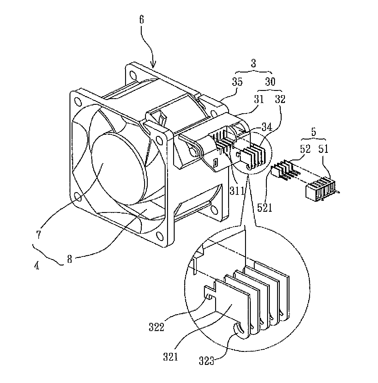
[0050]With reference to FIG. 7A, the hot swap fan 6A according to the invention includes a fan frame 3 and a terminal seat 30. The hot swap fan 6A can be an axial-flow fan. A corner of the fan frame 3 has an accommodating space 351 and two connecting parts 352. The connecting parts 352 are disposed adjacent to the accommodating space 351. In this embodiment, the connecting parts 352 are disposed on two opposite sides of the accommodating space 351. But the invention is not limited to this example.

[0051]The terminal seat 30 has a seat body 31 and two coupling elements 33. The coupling elements 33 are disposed on both sides of the seat body 31. In this embodiment, the coupling elements 33 are disposed on two opposite sides of the seat body 31 and corresponding to the connecting parts 352. The cross section of the seat body 31 has an L shape. The coupling elements 33 are disposed on both sides of the turning point of the seat body 31, and can be integrally formed with the seat body 31 ...

third embodiment

[0055]Please refer to FIGS. 8A and 8B. In the disclosed hot swap fan 6B, elements that are in common with fan 6A are assigned the same reference numerals, and will not be explicitly described herein, the description that follows being limited to the differences thereof. Specially, the hot swap fan 6B further includes a buckle 9 disposed in the connecting part 352. The buckle 9 has a sliding groove 91. The coupling elements 33 are disposed inside the sliding groove 91 in a slideable way. The terminal seat 30 is thereby limited to float in a single direction (e.g., Y direction) relative to the fan frame 3. Moreover, the width W′ of the seat body 31 is slightly smaller than the width W of the accommodating space 351 so that the terminal seat 30 can move in the Z direction relative to the fan frame 3.

[0056]The moving mechanism of the terminal seat 30 relative to the buckle 9 is described as follows. As shown in FIGS. 9A and 9B, the sliding groove 91 is a long circular through hole. Corr...


PUM


Abstract

A hot swap fan includes a fan frame and a terminal seat. A corner of the fan frame has an accommodating space and two connecting parts. The connecting parts are disposed adjacent to the accommodating space. The terminal seat has a seat body and two coupling elements. The coupling elements are disposed at two sides of the seat body and disposed corresponding to the connecting parts, respectively, so that the seat body can be disposed at the accommodating space. The diameters of the connecting parts are larger than those of the coupling elements so that the terminal base can be slightly movable in the accommodating space.

Description

CROSS REFERENCE TO RELATED APPLICATIONS[0001]The present invention is a continuation-in-part (C.I.P.) application of U.S. patent application Ser. No. 11 / 797,856, filed on May 8, 2006, which is entitled “Fan, Terminal Seat of Fan, and Method of Forming Terminal Seat”, and claims priority under 35 U.S.C. §119(a) on Patent Application Nos. 095148402 and 096204249 both filed in Taiwan, Republic of China on Dec. 22, 2006 and Mar. 16, 2007, respectively, the entire contents of which are hereby incorporated by reference.BACKGROUND OF THE INVENTION[0002]1. Field of Invention[0003]The invention relates to a terminal seat, a fan frame and a method of connecting a terminal to a seat body, and in particular, to a hot swap fan.[0004]2. Related Art[0005]With the enhancements in function and the operation speed of electronic systems, the heat generated by the electronic systems also increases. In order to make electronic systems work normally, the solution in the prior art is to provide a fan serv...

Claims


Application Information

Patent Timeline
IPC IPC(8): H01R13/00
CPCF04D25/0613F04D25/0693H05K7/20172F04D29/601
Inventor CHEN, CHIEN-CHANGYU, CHENG-SHUTAO, PENG-CHU
Owner DELTA ELECTRONICS INC
Why Eureka
Try Eureka