
Catalytic Alloy Hydrogen Sensor Apparatus and Process

a hydrogen sensor and catalyst alloy technology, applied in the field of hydrogen sensor, can solve the problems of limited solid-state sensor solutions to the problem of detecting hydrogen concentration, low device production yield, and limited experimental laboratory environmen

Inactive Publication Date: 2008-06-26
UOP LLC
View PDF15 Cites 26 Cited by
  • Summary
  • Abstract
  • Description
  • Claims
  • Application Information

AI Technical Summary

Benefits of technology

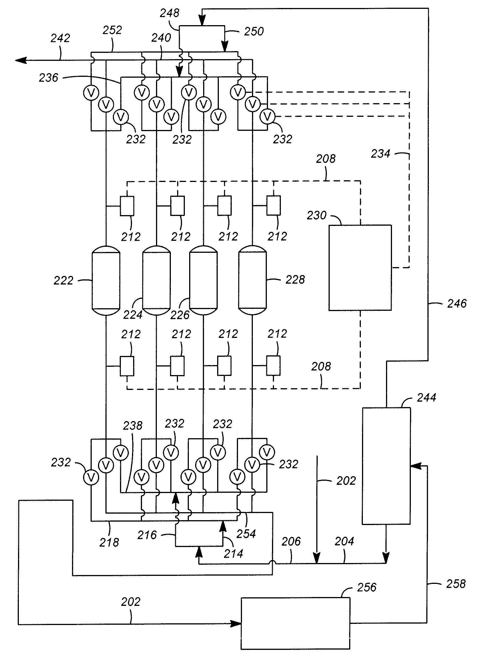
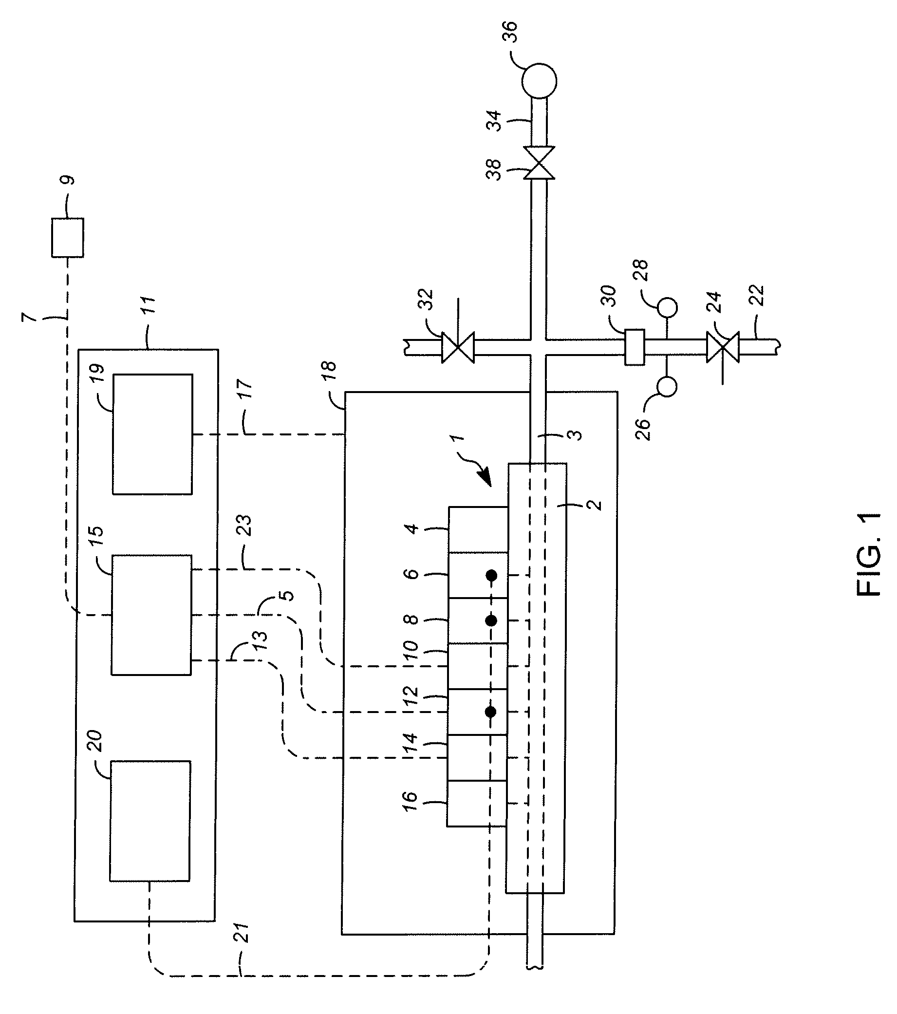
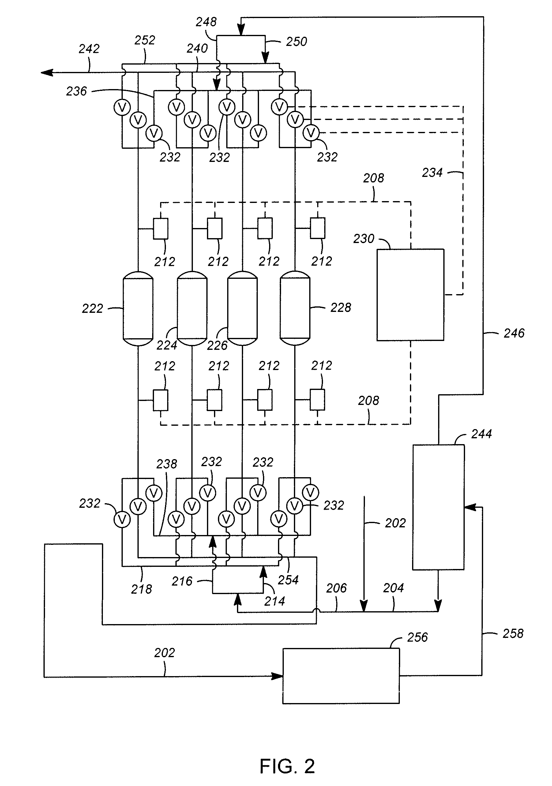
[0015]The invention is an apparatus comprising a processing unit; a feed conduit and an effluent conduit connected to the processing unit; at least one operating parameter device associated with the processing unit, the feed conduit, the effluent conduit or a combination thereof; a catalytic alloy hydrogen sensor in fluid communication with the processing unit, the feed conduit, the effluent conduit or a combination thereof; and a computer processor electrically connected to the catalytic alloy hydrogen sensor. The apparatus may also have at least one operating parameter device and an electrical connection between the computer processor and at least one of the operating parameter devices. The apparatus may be used for the control of a processing unit or operation. A pressure indicator may be positioned to indicate the pressure of fluid passing through the catalytic alloy hydrogen sensor and there may be an electrical connection between the computer processor and the pressure indicator. The catalytic alloy hydrogen sensor may be a palladium-nickel catalytic alloy hydrogen sensor.

Problems solved by technology

Prior solid state sensor solutions to the problem of detecting hydrogen concentrations had been generally limited to detecting low concentrations of hydrogen.
It was, however, primarily limited to an experimental laboratory environment due to the difficulties encountered in manufacturing such a sensor.
Difficulties in producing such semiconductor devices due to the specialized materials were believed to result in low device production yields.
An economically feasible commercial hydrogen sensor is difficult to obtain if yields are under an acceptable level.
Not all hydrogen sensors in the art will function adequately in every application where hydrogen is to be monitored or measured.
Sensors employing differing technologies have unique limitations.

Method used


Image

  • Catalytic Alloy Hydrogen Sensor Apparatus and Process
  • Catalytic Alloy Hydrogen Sensor Apparatus and Process
  • Catalytic Alloy Hydrogen Sensor Apparatus and Process

Examples


example

[0062]A total isomerization process was monitored using the present invention and adjustments were made to flow rates and cycle times of the total isomerization process based on data collected using the present invention. Previously, gas chromatograph (GC) systems were used to periodically monitor the adsorptive separation portion of the total isomerization process and adjust parameters to optimize the refining process. Therefore, a GC system was also set up to verify the data collected using the catalytic alloy hydrogen sensor. The GC system was used to monitor hydrocarbons and hydrogen at specific locations within the total isomerization process and to compare the results to data collected from the present invention. The GC system had several drawbacks. First, the GC system required a complicated manifold and care was required to watch for and correct leaks. Over time, hydrocarbons in the hydrogen stream operates to deactivate the GC system and the sampling frequency is limited to...


PUM


Abstract

An apparatus comprising a processing unit; a feed conduit and an effluent conduit connected to the processing unit; at least one operating parameter device associated with the processing unit, the feed conduit, the effluent conduit or a combination thereof; a catalytic alloy hydrogen sensor in fluid communication with the processing unit, the feed conduit, the effluent conduit or a combination thereof; and a computer processor electrically connected to the catalytic alloy hydrogen sensor, has been developed. The apparatus may also have at least one operating parameter device and an electrical connection between the computer processor and at least one of the operating parameter devices. The apparatus may be used for the control of a processing unit or operation. A pressure indicator may be positioned to indicate the pressure of fluid passing through the catalytic alloy hydrogen sensor and there may be an electrical connection between the computer processor and the pressure indicator. The catalytic alloy hydrogen sensor may be a palladium-nickel catalytic alloy hydrogen sensor.

Description

FIELD OF THE INVENTION[0001]The present invention is related to hydrogen sensors, and more particularly, to an assembly for a modular hydrogen sensor system using a catalytic alloy hydrogen sensor.BACKGROUND OF THE INVENTION[0002]Chemical sensing equipment has long been helpful in monitoring processes. Hydrogen sensors in particular have been employed in a variety of applications. Improvements in hydrogen sensors have resulted in sensors that are capable of detecting a wide range of hydrogen concentrations with reproducible signals. They respond rapidly and reversibly to changes in hydrogen concentration and exhibit resistance to poisoning.[0003]One particular class of hydrogen sensors began in the early 1990s when Sandia National Laboratory developed a single-chip hydrogen sensor that utilized Palladium-Nickel (PdNi) catalytic alloy as hydrogen gas sensors. The PdNi catalytic alloy was deposited on a metal-oxide semiconductor (CMOS), see U.S. Pat. No. 5,279,795 which is incorporate...

Claims


Application Information

Patent Timeline
Patent Type & Authority Applications(United States)
IPC IPC(8): G05B21/00
CPCG01N33/005
Inventor GALLOWAY, DOUGLAS B.HOLT, RANDALL E.BULLEN, PATRICK J.
Owner UOP LLC
Learn More