Buckle structure of waist belt
- Summary
- Abstract
- Description
- Claims
- Application Information
AI Technical Summary
Benefits of technology
Problems solved by technology
Method used
Image

Examples
first embodiment
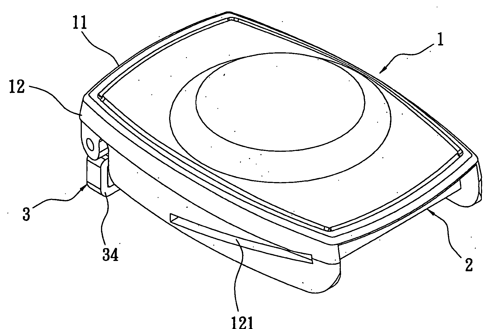
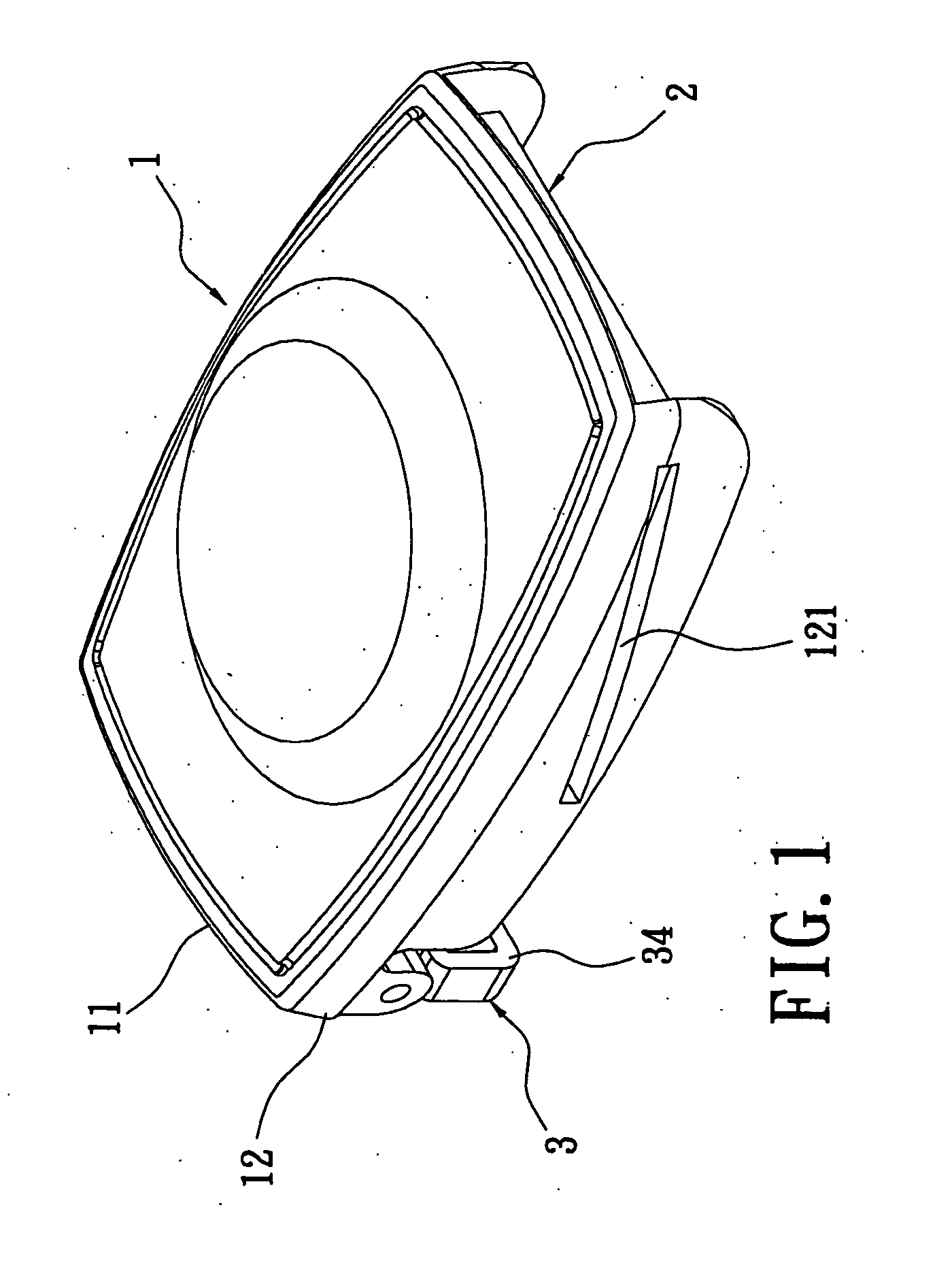
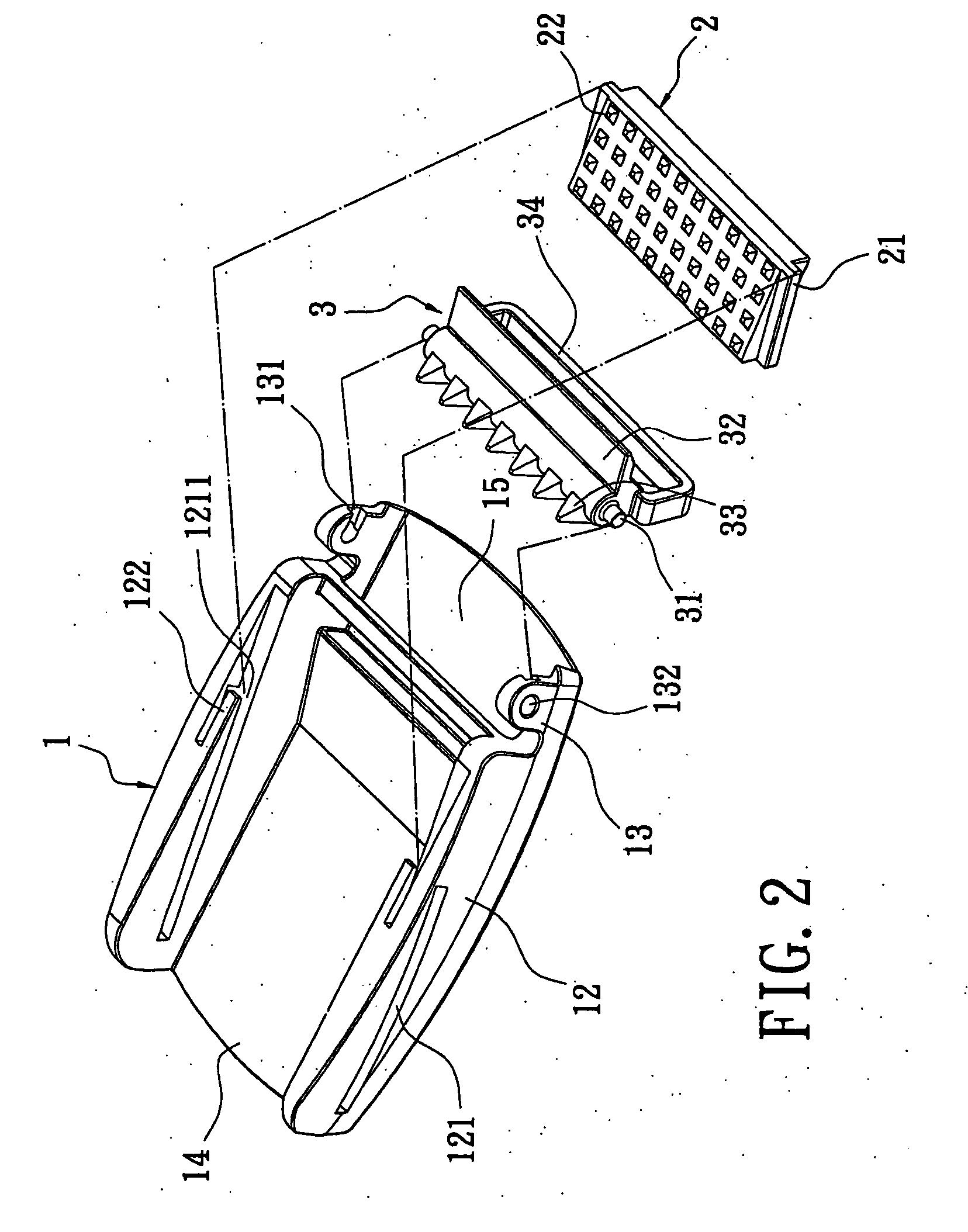
[0027]Referring to FIGS. 1 and 2, they illustrate a buckle structure of a waist belt according to the present invention. The buckle structure includes a housing 1, a sliding wedge 2 and a pivotal piece 3. The housing 1 includes a top plate 11 and two side plates 12. Each of the two side plates 12 has a guiding slot 121 which is slant. The sliding wedge 2 is positioned at the bottom of the housing 1 and has a pair of projection portions 21 protruding from its two sides and corresponding to the guiding slots 121. Each of the guiding slots 121 has an opening 1211, and the sliding wedge 2 slides along the guiding slots 121 through the opening 1211 and the projection portions 21 are inserted into the guiding slots 121.
[0028]A plurality of stoppers 22 is positioned on top surface of the sliding wedge 2, and each of the side plates 12 has a stopper pin 122 at its bottom. The stopper pins 122 are respectively positioned below the openings 1211 so that the sliding wedge 2 will not be loosed ...
second embodiment
[0032]Referring to FIGS. 5 and 6, the present invention is shown. Two grooves 23 are respectively positioned at the two side of the sliding wedge 2. One of the grooves 23 is in vicinity of the top of the sliding wedge 2 and front of the projection portions 21, and the other of the groove 23 is in vicinity of the bottom of the sliding wedge 2 and rear of the projection portions 21. Two holes 24 are respectively formed on the projection portions 21, and each of the holes 24 is used to receive one resilient element 25. One ends of the resilient elements 25 protrude out of the holes 24.
[0033]The sliding wedge 2 movably meshes with a belt adjustment unit 5. The belt adjustment unit 5 includes a hand-push portion 51 and a snap hook 52. The hand-push portion 51 has a concave top surface and ergonomic so that it is convenient for user to push. The bottom of the hand-push portion 51 is integrally formed with the snap hook 52 so that the resilient elements 25 protruding out of the holes 24 ab...
PUM
 Abstract
Description
Claims
Application Information
 - Generate Ideas
- Intellectual Property
- Life Sciences
- Materials
- Tech Scout
- Unparalleled Data Quality
- Higher Quality Content
- 60% Fewer Hallucinations
Browse by: Latest US Patents, China's latest patents, Technical Efficacy Thesaurus, Application Domain, Technology Topic, Popular Technical Reports.
© 2025 PatSnap. All rights reserved.Legal|Privacy policy|Modern Slavery Act Transparency Statement|Sitemap|About US| Contact US: help@patsnap.com