Skin Needle Manufacturing Apparatus and Skin Needle Manufacturing Method

a manufacturing method and manufacturing method technology, applied in the field of manufacturing apparatus and manufacturing methods for needles, can solve the problems of high labor intensity, high labor intensity, and inability to accurately shape molds for forming micro-needles, so as to save labor intensity and facilitate manufacturing, the effect of saving labor intensity

Active Publication Date: 2008-07-03
NABLESCO CORP
View PDF0 Cites 37 Cited by
  • Summary
  • Abstract
  • Description
  • Claims
  • Application Information

AI Technical Summary

Benefits of technology

[0030]This two-stage skin needle manufacturing apparatus may further comprises second heat generating means configured to adjust the second material to a predetermined temperature by heating the material installation member, and second control means configured to control the second heat generating means and the second moving means. This control means operates each of the second heat generating means and the second moving means to form the second-stage skin needle. Consequently, the effort of a worker operating the apparatus can be saved. Also, the two-stage skin needle can more easily be manufactured.
[0031]In a case where the first-stage needle and the second-stage needle use different materials, respectively, the needles can effectively be used by appropriately preparing the ingredients of the material of each of the needles. The material of each of the first-stage needle and the second-stage needle is composed mainly of the biodegradable substances. In a case where a material further including functional substances to be injected to skin is used as the material of the second-stage needle, the functional substances can effectively be injected into the inner part of the skin without waste.

Problems solved by technology

In a case where the number of the molds is large, the time and effort for preparing the molds and those for managing the molds are very large.
Additionally, the mold for forming micro-needles needs precisely shaping and is apt to be costly.
Thus, the conventional manufacturing method has a problem that the time, the effort and the cost are excessive.
Such a problem is inevitable, especially, in cases where it is intended to manufacture various kinds of skin needles little by little and where it is intended to tentatively manufacture a small number of skin needles.

Method used


Image

  • Skin Needle Manufacturing Apparatus and Skin Needle Manufacturing Method
  • Skin Needle Manufacturing Apparatus and Skin Needle Manufacturing Method
  • Skin Needle Manufacturing Apparatus and Skin Needle Manufacturing Method

Examples


first embodiment

[0075]First, the configuration of a skin needle manufacturing apparatus 10 according to a first embodiment of the invention is described below. The skin needle manufacturing apparatus 10 according to the first embodiment can manufacture skin needles which are several hundreds micrometers in length. Thus, the skin needle manufacturing apparatus 10 are of the material discharge type that discharges a material for the skin needles from a tip end of the pin member to the base.

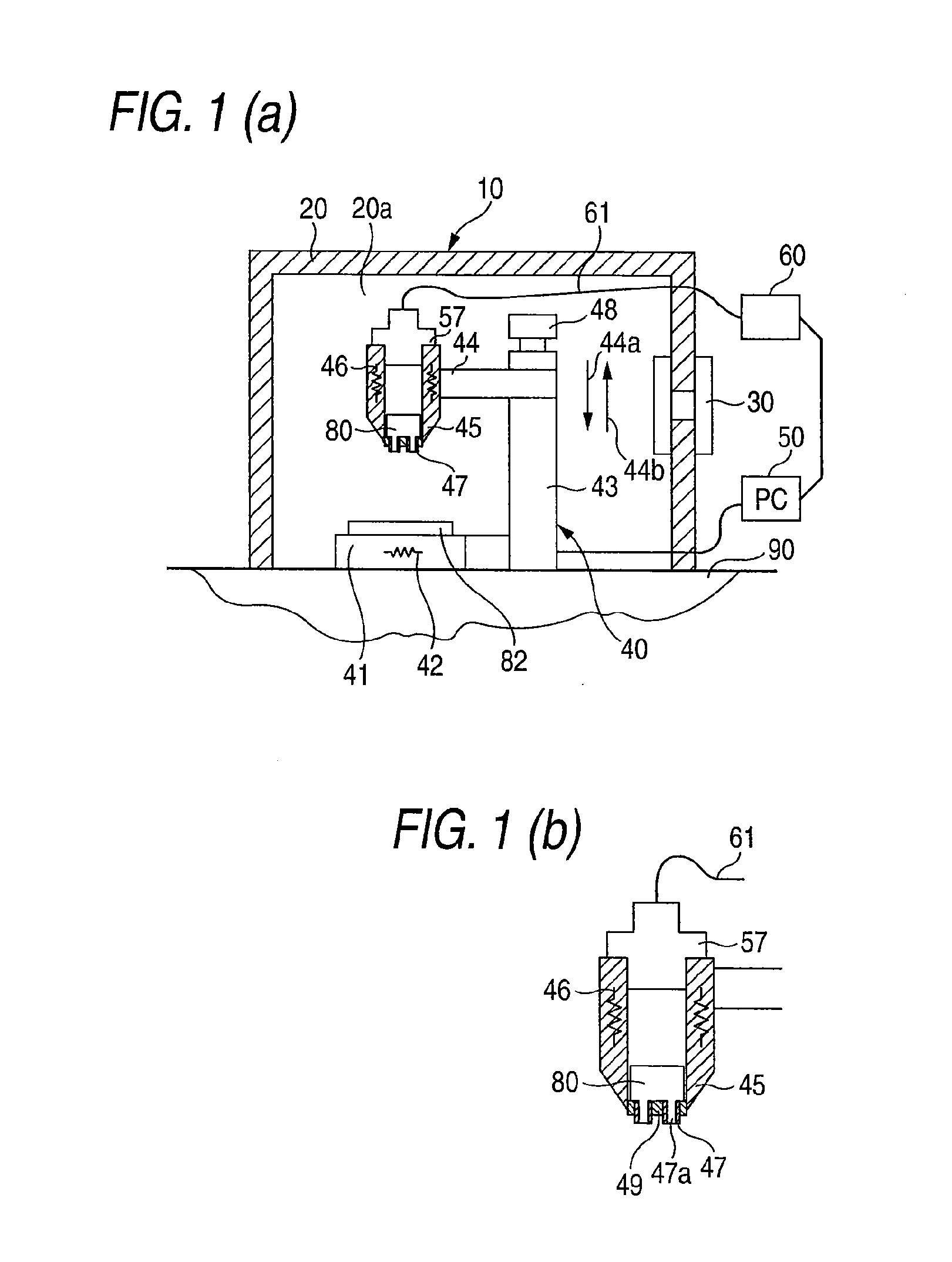
[0076]As illustrated in FIG. 1(a), the skin needle manufacturing apparatus 10 according to the first embodiment has a wall portion 20 as an outer case. The wall portion 20 is installed on a pedestal 90. A chamber 20a is formed in the wall portion 20. A humidity maintaining means 30, which maintains the inner humidity of the chamber 20a within a predetermined range (i.e., a range between 30% and 60% and between ±5% of a set humidity), is installed in the wall portion 20. A body 40 of the skin needle manufacturing ap...

second embodiment

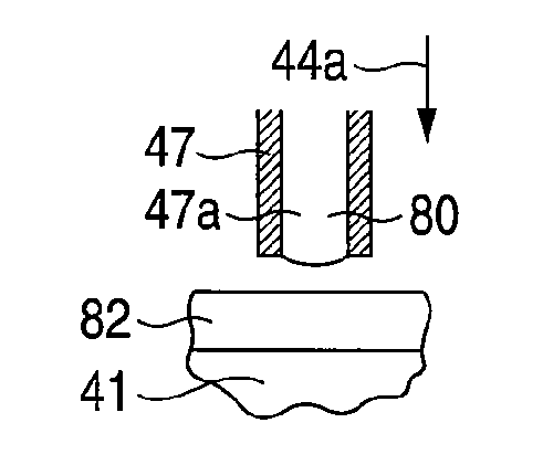
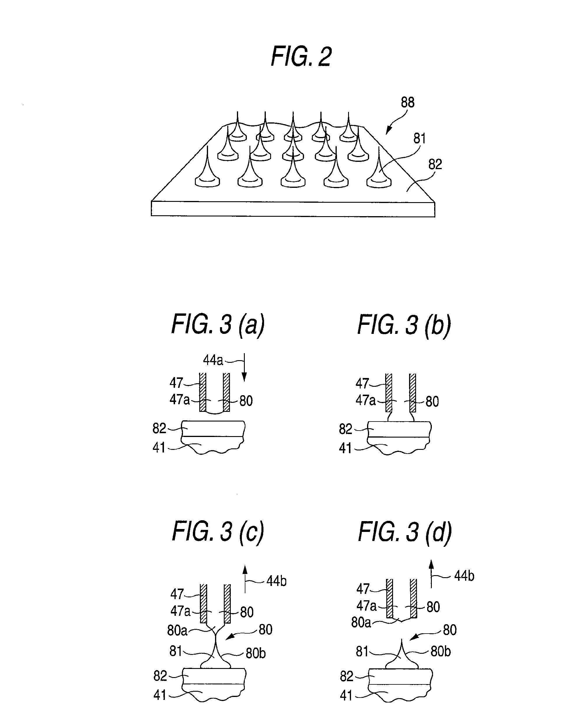
[0099]A skin needle manufacturing apparatus 110 according to a second embodiment of the invention is described below. The skin needle manufacturing apparatus 10 of the material discharge type discharges the material of the needle from the tip end of the pin member 47 to the base 82. In contrast, the skin needle manufacturing apparatus 110 described below is of the material drawing-up type that forms the base of the material of the needle and that forms a needle by melting a part of the base. The skin needle manufacturing apparatus 110 of the material drawing-up type differs from that of the material discharge type basically only in the pin member 47 and peripheral devices thereof. Most of the constituent elements of the skin needle manufacturing apparatus 110 of the material drawing-up type are the same as the corresponding elements of the apparatus of the material discharge type. Therefore, the constituent elements of the skin needle manufacturing apparatus 110 of the material draw...


PUM

PropertyMeasurementUnit
lengthaaaaaaaaaa
humidityaaaaaaaaaa
humidityaaaaaaaaaa

Abstract

In a skin needle manufacturing apparatus 10, a material melted in a syringe 45 is discharged from a fine hole 47a of a pin member 47 and is caused to adhere to a base 48. A computer 50 causes a drive mechanism 48 to separate the pin member 47 from the base 48. Then, the material 80 having adhered to the pin member 47 and the base 48 is drawn out. A projection portion 48b formed of a part of the material 80, which has adhered to the base 48, is formed into a skin needle 81. Consequently, a skin needle can relatively easily be manufactured without requiring excessive time, effort, and cost.

Description

CROSS-REFERENCE TO RELATED APPLICATIONS[0001]This application is a Section 371 of International Application No. PCT / JP2005 / 024136, filed Dec. 28, 2005, which was published in the Japanese language on Jul. 27, 2006, under International Publication No. WO 2006 / 077742 A1 and the disclosure of which is incorporated herein by reference.BACKGROUND OF THE INVENTION[0002]The present invention relates to a manufacturing apparatus and method for manufacturing needles that are stabbed into skin and that are used for medical treatment and beautification.[0003]Skin needles can stab into human skin by being arranged to erect on, for example, the top surface of a sheet-like base, whose length ranges from 50 μm to 1 mm, and being held thereto. In a case where the needles are finely formed, a stabbed person feels no pain. In a case where the skin needle is formed of a material which employs biodegradable substances (e.g., maltose (or malt sugar) and polylactic acid) as major ingredients and is mixed...

Claims


Application Information

Patent Timeline
Patent Type & Authority Applications(United States)
IPC IPC(8): B29C51/08B29C47/12B29C48/30
CPCA61H39/086A61M2037/0053A61M2037/0046A61M37/0015A61P3/10
Inventor MUKAI, NOBUYUKIKURAMOTO, SHUKENTAKAHASHI, TSUTOMUOONUMA, YOSHINORI
Owner NABLESCO CORP
Why Eureka
Try Eureka