Axial fan motor

a technology of axial fan and motor, which is applied in the direction of dynamo-electric machines, structural associations, supports/encloses/casings, etc., can solve the problems of increasing the noise of electromagnetic exciting force, the inability to recycle resources, and the inability to rotate the vanes in the axial fan. , to achieve the effect of reducing structural noise and reducing nois

Active Publication Date: 2008-07-03
JAPAN SERVO CO LTD
View PDF8 Cites 17 Cited by
  • Summary
  • Abstract
  • Description
  • Claims
  • Application Information

AI Technical Summary

Benefits of technology

[0012]In order to overcome the problems described above, preferred embodiments of the present invention provide an axial fan motor generating little noise and capable reducing structural noise generated by vibrations of the motor, etc., even when the axial fan motor is incorporated into various devices.

Problems solved by technology

When the air flow capacity of an axial fan motor is increased, however, there is a tendency that noise due to an electromagnetic exciting force and rotation of vanes in the axial fan is increased.
A stator core and a sleeve, which supports the stator core, in conventional fan motors and blowers are joined together by measures such as bonding, caulking, welding, etc., but when a stator core is fixed to the sleeve by such measures, disassembly cannot be performed unless the sleeve is broken, so that recycling of the resource cannot be achieved.

Method used


Image

  • Axial fan motor
  • Axial fan motor
  • Axial fan motor

Examples


first preferred embodiment

[0063]First, a first preferred embodiment of the present invention is described with reference to FIGS. 1 to 9. In addition, the same reference numerals in the respective figures denote the same parts.

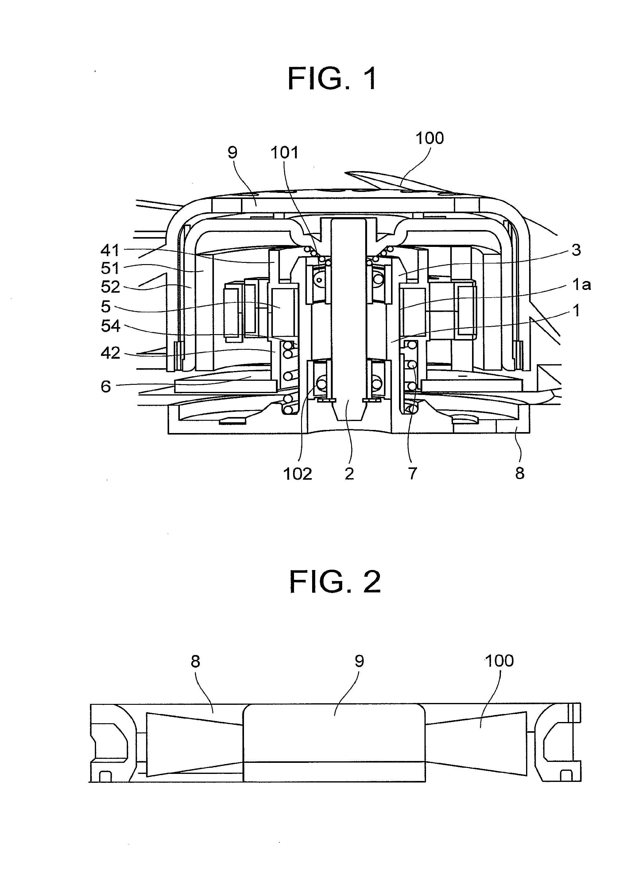
[0064]FIG. 1 is a cross sectional view showing an axial fan motor according to a first preferred embodiment of the present invention.

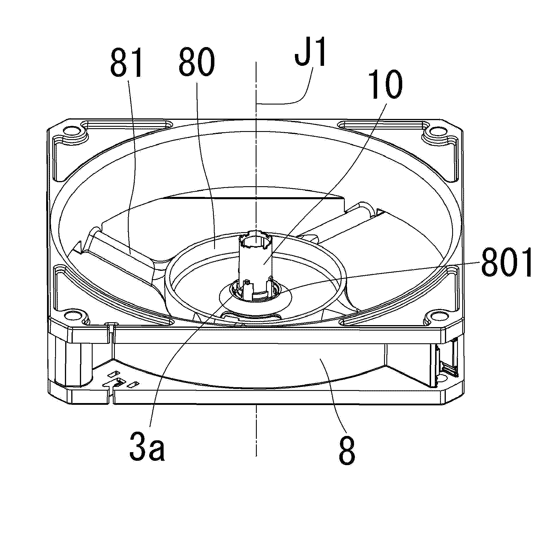
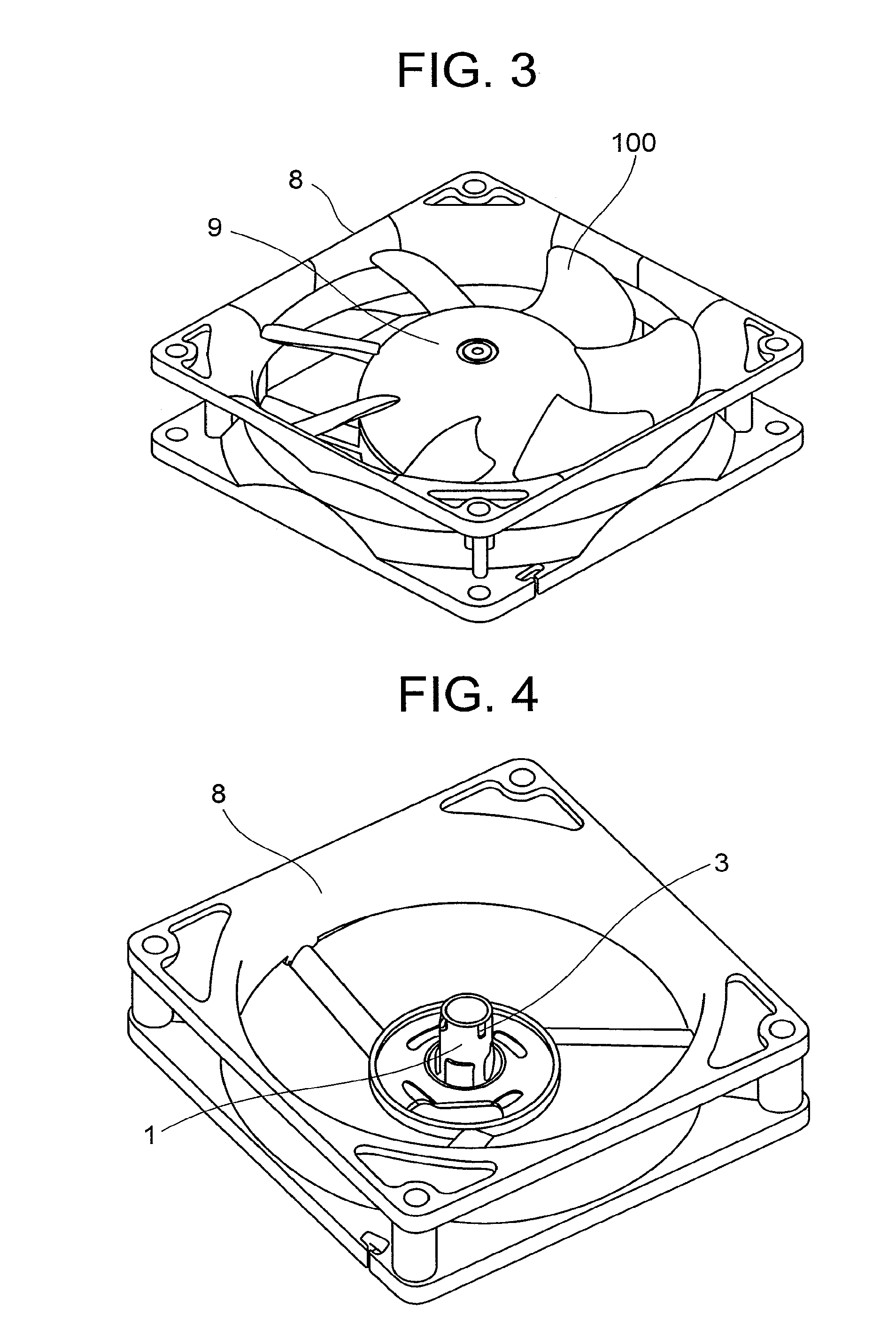
[0065]FIG. 2 is a view showing an entire construction of the axial fan motor according to the first preferred embodiment of the present invention. In FIGS. 1 and 2, the reference numeral 1 denotes a sleeve through which a rotating shaft 2 of the axial fan motor extends. The reference numeral 3 denotes stoppers mounted to a tip end of the sleeve 1. The shaft 2 and the sleeve 1 are mounted with bearings 101, 102 therebetween. The reference numeral 41 denotes an upper insulator and 42 a lower insulator. The reference numeral 5 denotes a stator core and a fan to which a rotor including a magnet 51 and a rotor case 52 is provided, the fan being mounted to an o...

second preferred embodiment

[0078]Next, a second preferred embodiment of the present invention will be described with reference to FIGS. 10 to 13. In addition, the same reference numerals in the respective drawings denote the same parts.

[0079]FIG. 10 is a perspective view of a venturi. As shown in FIG. 10, an upper end of a sleeve 1 mounted to a central portion of the venturi 8 is circular-shaped and downwardly concave-shaped and is provided on a portion of a circumference thereof with a positioning notch 111. An upper insulator described below is fitted into the circular-shaped recess.

[0080]FIG. 11 is a perspective view of the upper insulator 41. The upper insulator 41 is provided with a bearing support 413. A bearing is fitted inside the bearing support 413.

[0081]FIG. 12 is a perspective view of the upper insulator 41 as viewed from below. As shown in FIG. 12, a positioning projection 414 is mounted to an underside of the upper insulator 41 to be fitted into the notch 111 on the upper portion of the sleeve s...

third preferred embodiment

[0087]Subsequently, a third preferred embodiment of the present invention will be described with reference to FIG. 14 to 18. In addition, the same reference numerals in the respective drawings denote the same parts.

[0088]FIG. 14 is a perspective view of a venturi. As shown in FIG. 14, an upper end of a sleeve 1 mounted to a central portion of the venturi 8 is circular-shaped and downwardly concave-shaped to include large and small semi-circular notches in eight locations on a circumference thereof. The notches will be described with reference to an enlarged perspective view of FIG. 15, which shows the vicinity of the sleeve 1. As shown in FIG. 15, two kinds of semi-circular notches are shown; passage notches 112 and positioning notches 113 are provided, and the positioning notches 113 have a smaller radius than the radius of the passage notches 112. Two of these notches define a set and are arranged very close to each other, four sets in total being arranged across from each other, ...


PUM


Abstract

A motor includes a rotor portion including a shaft and a rotor magnet rotatable about a center axis, an armature arranged opposite to the rotor magnet to generate a torque therebetween, a circuit board arranged below the armature in an axial direction substantially parallel to the center axis and including a control circuit controlling rotation of the rotor portion, and a base portion including a bearing holder which supports the armature on its outer side surface and the shaft on its inner side surface via a bearing member. The armature is pressed against the bearing holder in the axial direction with an elastic member.

Description

BACKGROUND OF THE INVENTION[0001]1. Field of the Invention[0002]The present invention relates to an axial fan motor.[0003]2. Description of the Related Art[0004]An axial fan motor for cooling heat generating electronic parts is generally mounted on household electric appliances and various OA / IT equipment. Recently, demand for a large air flow capacity of the axial fan has increased because of the increase in the heat generated by, and the reduction in product costs, of household electric appliance and various OA / IT equipment. When the air flow capacity of an axial fan motor is increased, however, there is a tendency that noise due to an electromagnetic exciting force and rotation of vanes in the axial fan is increased. Further, a demand for noise reduction has increased for the pursuit of a more comfortable environment, and improvements corresponding thereto have been developed.[0005]In JP-A-10-159792, vibration reduction is intended by providing vibration isolating rubber between ...

Claims


Application Information

Patent Timeline
Patent Type & Authority Applications(United States)
IPC IPC(8): H02K5/16H02K7/14H02K11/00
CPCH02K7/14H02K1/182
Inventor SEKIGUCHI, OSAMUTANNO, TAROKATO, YOSHIHIKOHIOKI, TETSUYAHIGO, ASAHI
Owner JAPAN SERVO CO LTD
Why Eureka
Try Eureka