Current Sensor and Method for Motor Control
a current sensor and motor control technology, applied in the direction of electric motor control, moving-iron instruments, instruments, etc., can solve the problems of external synchronous signal, limited working frequency to maximum 20 khz, damage to the low-power circuitry of the motor control unit,
- Summary
- Abstract
- Description
- Claims
- Application Information
AI Technical Summary
Benefits of technology
Problems solved by technology
Method used
Image
Examples
example 1
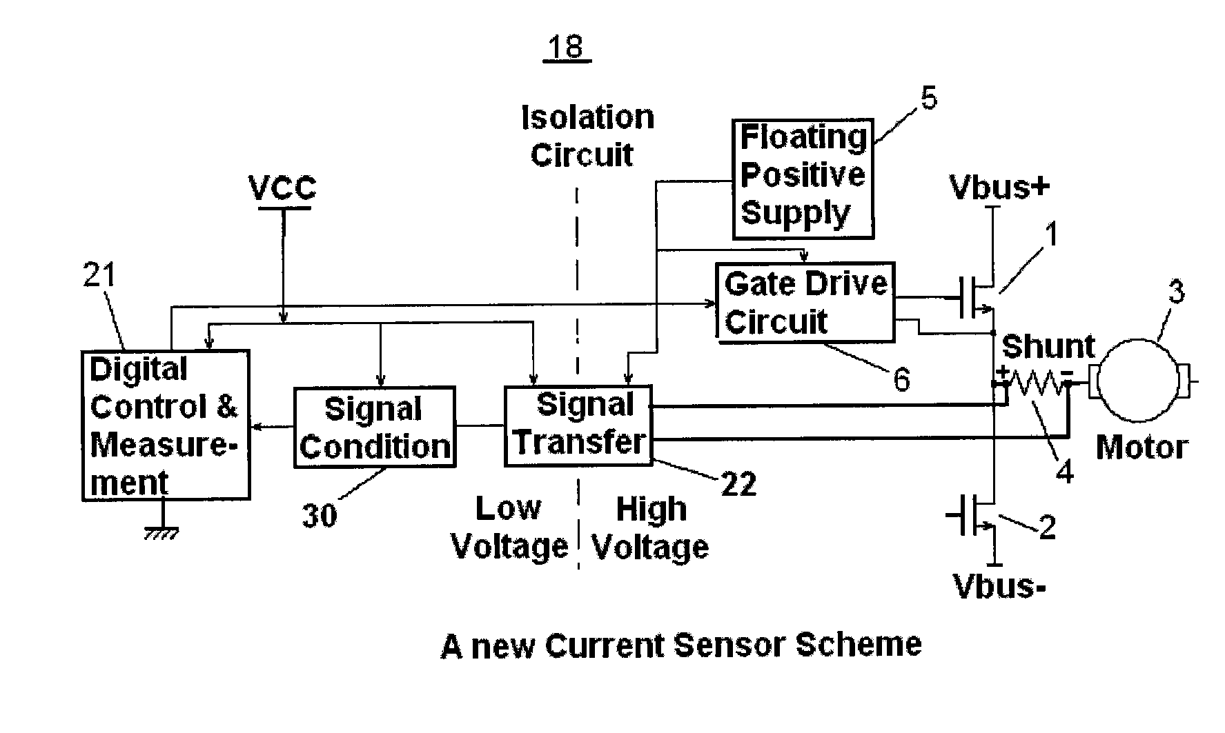
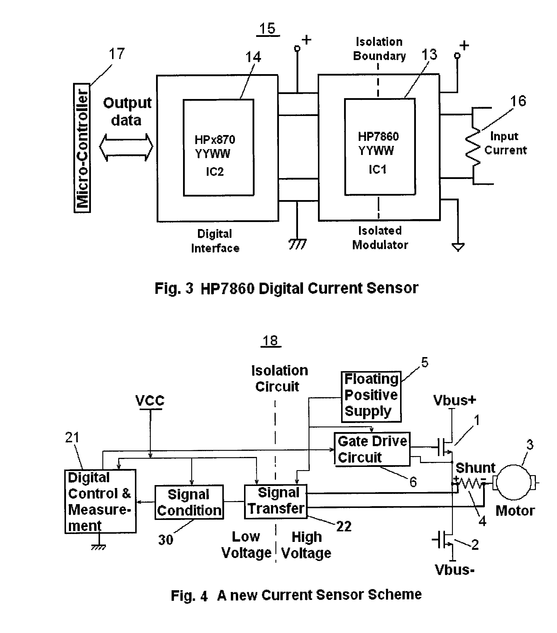
[0082]In Example 1, for the purpose of illustration, the following assumptions are made:[0083]1) Saturation voltage of component switches 1 and 2 are about 2 volts.[0084]2) Voltage drops on damper diodes D1 an D2 when clamping are about 0.7 volts.[0085]3) The range of current on shunt resistor 4 is from −20 amps to +20 amps.[0086]4) The resistance of the shunt resistor 4 is 0.01 ohm.
We further assume in this example that the current across the shunt resistor is −20 amps.
[0087]V2-VC=(U2H-U1H)*(RfRin)=(VA-VB)*RfRin=-20amp*0.01ohm*7.5k1.0k=-1.5V(1)V2-V1=(V2-VC)+(VC-V1)=-1.5V+1.5V=0.0V(2)
Since the saturation voltage on switching component 2 is V1=VA=2V . . . (3)
[0088]WehaveV2=V1+0.0V=2V(4)U2L=V2+0.7V=2.7VThen(5)U1L=V1+0.7V=2.7V(6)Atlast,V(ADCin)-V(ADC_GND)=V2L-V1L=2.7V-2.7V=0.0V(7)WhereV(ADC_GND)=0V.(8)
example 2
[0089]In Example 2, for the purpose of illustration, the following assumptions are made:[0090]1) Saturation voltage of component switches 1 and 2 are about 2 volts.[0091]2) Voltage drops on damper diodes D1 an D2 when clamping are about 0.7 volts.[0092]3) The range of current on shunt resistor 4 is from −20 amps to +20 amps.[0093]4) The resistance of the shunt resistor 4 is 0.01 ohm.
We further assume in this example that the current across the shunt resistor is +20 amps.
[0094]V2-VC=(U2H-U1H)*(RfRin)=(VA-VB)*RfRin=+20amp*0.01ohm*7.5k1.0k=1.5V(9)V2-V1=(V2-VC)+(VC-V1)=1.5V+1.5V=3.0V(10)
Since the saturation voltage on switch component 2 is V1=VA=2V . . . (11)
[0095]WehaveV2=V1+3V=5V(12)U2L=V2+0.7V=5.7VThen(13)U1L=V1+0.7V=2.7V(14)Atlast,V(ADCin)-V(ADC_GND)=V2L-V1L=5.7V-2.7V=3.0V(15)WhereV(ADC_GND)=0V.(16)
example 3
[0096]In Example 3, for the purpose of illustration, the following assumptions are made:[0097]1) Saturation voltage of component switches 1 and 2 are about 2 volts.[0098]2) Voltage drops on damper diodes D1 an D2 when clamping are about 0.7 volts.[0099]3) The range of current on shunt resistor 4 is from −20 amps to +20 amps.[0100]4) The resistance of the shunt resistor 4 is 0.01 ohm.
We further assume in this example that the current across the shunt resistor is 0 amps.
[0101]V2-VC=(U2H-U1H)*(RfRin)=(VA-VB)*RfRin=+0.0amp*0.01ohm*7.5k1.0k=0.0V(17)V2-V1=(V2-VC)+(VC-V1)=0.0V+1.5V=1.5V(18)
Since the saturation voltage on switch component 2 is V1=VA=2V . . . (19)
[0102]WehaveV2=V1+1.5V=3.5V(20)U2L=V2+0.7V=4.2V(21)ThenU1L=V1+0.7V=2.7V(22)Atlast,V(ADCin)-V(ADC_GND)=V2L-V1L=4.2V-2.7V=1.5V(23)WhereV(ADC_GND)=0V.(24)
[0103]It is understood that the above description of the various embodiment of the present invention are illustrative and not limiting as to the structures, methods and benefits of th...
PUM
 Abstract
Description
Claims
Application Information
 - R&D
- Intellectual Property
- Life Sciences
- Materials
- Tech Scout
- Unparalleled Data Quality
- Higher Quality Content
- 60% Fewer Hallucinations
Browse by: Latest US Patents, China's latest patents, Technical Efficacy Thesaurus, Application Domain, Technology Topic, Popular Technical Reports.
© 2025 PatSnap. All rights reserved.Legal|Privacy policy|Modern Slavery Act Transparency Statement|Sitemap|About US| Contact US: help@patsnap.com


