Ultra Broadband 10-W CW Integrated Limiter

a technology of cw limiter and ultra-fast broadband, which is applied in the direction of excess voltage/current emergency protective arrangement, waveguide type device, etc., can solve the problems of low power limiter with less than 0.3 db insertion loss, circuits are susceptible to damage, and no broadband 10-w cw limiter product is availabl

Active Publication Date: 2008-07-03
CAES SYST LLC
View PDF99 Cites 8 Cited by
  • Summary
  • Abstract
  • Description
  • Claims
  • Application Information

AI Technical Summary

Benefits of technology

[0009]These and other features of the invention will be mor

Problems solved by technology

Due to the fine geometry used in MMIC transistors, these circuits are susceptible to damage from high-power spurious electromagnetic radiation, e.g., from microwave transmitters or nuclear electromagnetic pulses.
At present, howeve

Method used


Image

  • Ultra Broadband 10-W CW Integrated Limiter
  • Ultra Broadband 10-W CW Integrated Limiter
  • Ultra Broadband 10-W CW Integrated Limiter

Examples


Embodiment Construction

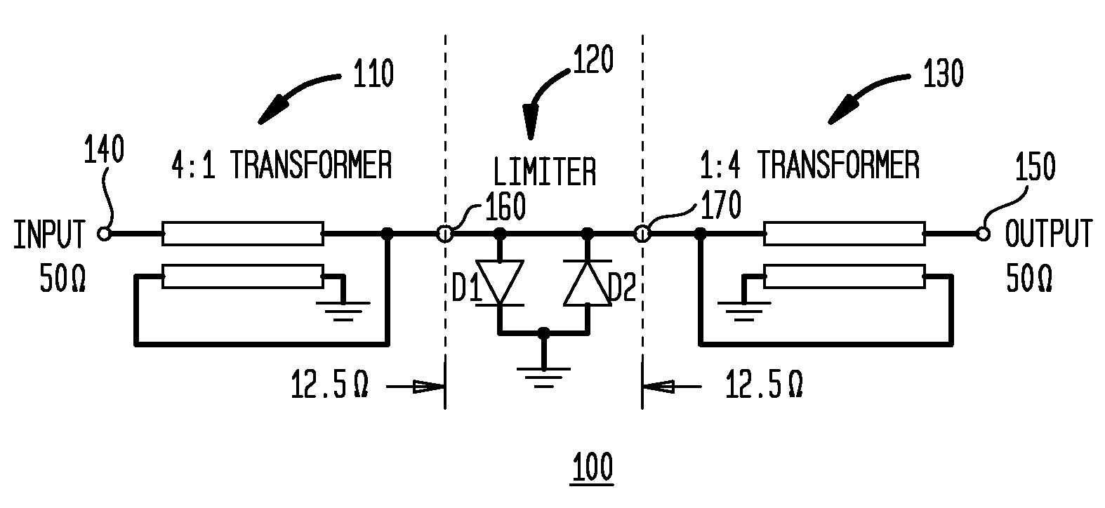
[0028]FIG. 1 shows an embodiment of a broadband power limiter in accordance with the invention. This ultra broadband high power limiter can handle greater than 10 watts of CW power and may be monolithically integrated on GaAs substrate as a stand-alone product or with low noise amplifier manufactured using existing multi-function self-aligned gate processes (e.g., M / A-COM's MSAG® process).

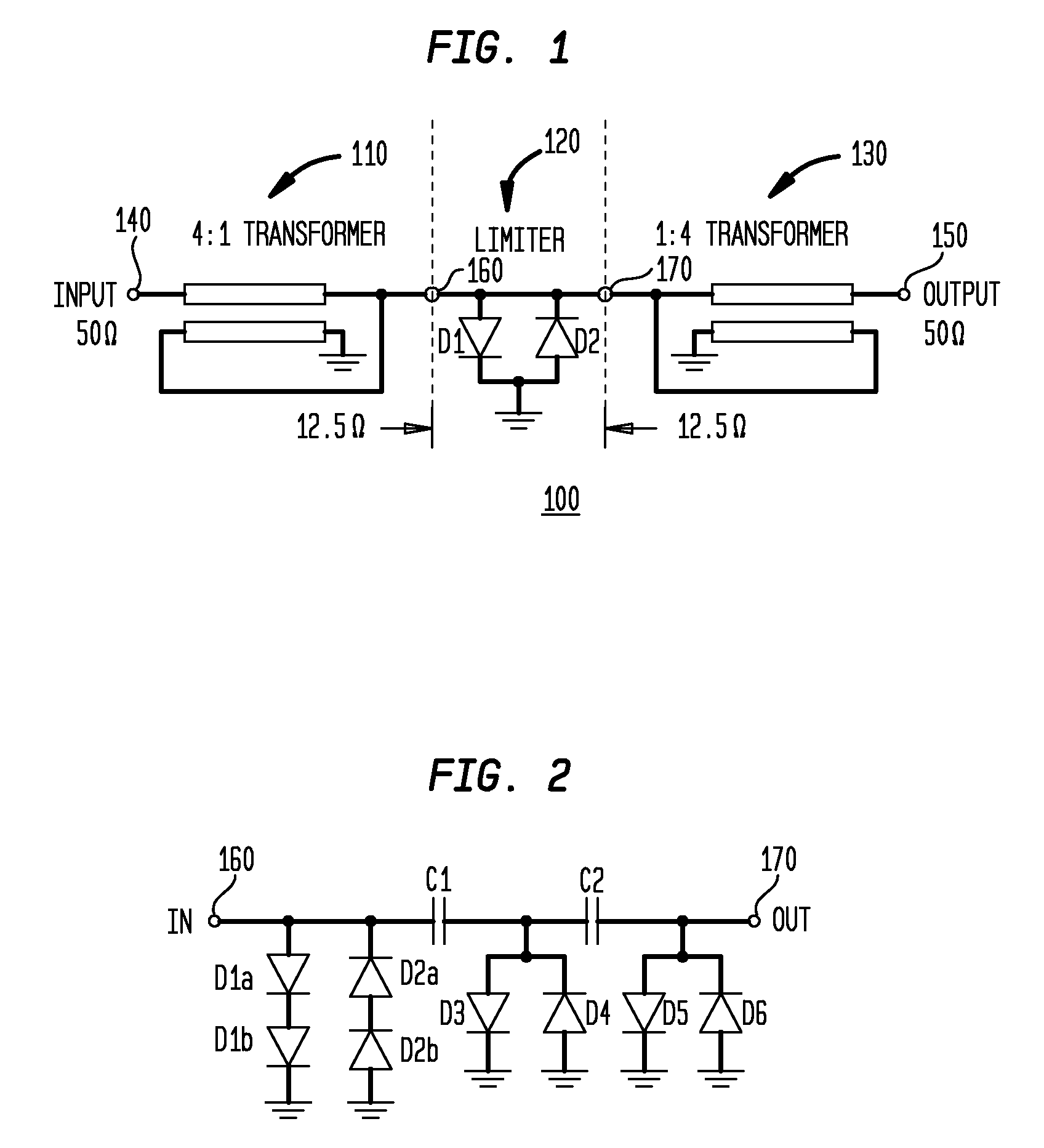
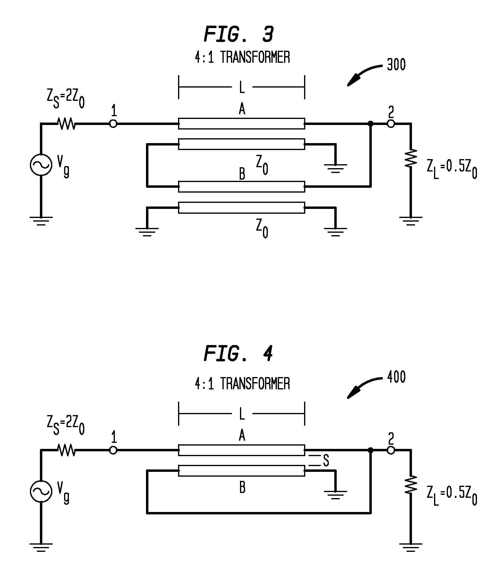
[0029]With reference to FIG. 1, the broadband power limiter 100 comprises: a first broadband impedance transformer 110 connected to the input terminal 140 for transforming the input impedance from a first impedance (e.g., 50 ohms or 75 ohms) to an intermediate impedance lower than the first (e.g., 12.5 ohms or 18.75 ohms); a limiter circuit 120 including one or more shunt diodes D1, D2; and a second broadband impedance transformer 130 for transforming the intermediate impedance to an output impedance at the output terminal 150. The first broadband impedance transformer 110 is preferably a step-down...


PUM


Abstract

The invention provides a novel broadband power limiter having improved frequency characteristics and power capacity, suitable for use with GaAs low-noise amplifier circuits. The power limiter includes a shunt diode circuit and two impedance transformers. The first transformer is a step-down impedance transformer connected between the shunt diode circuit and the input to the limiter, and the second transformer is a step-up impedance transformer connected between the shunt diode circuit and the output of the limiter. The invention further provides a method for limiting the power of an input signal, comprising the steps of: transforming the input signal from the input impedance to an intermediate impedance; shunting a portion of the input signal to ground; and transforming a remaining portion of the input signal from the intermediate impedance to an output impedance. The invention further provides a novel impedance transformer suitable for use in the broadband power limiter and a method for providing such an impedance transformer.

Description

FIELD OF THE INVENTION[0001]The present invention relates to a limiter for use in microwave communication systems.BACKGROUND OF THE INVENTION[0002]Monolithic microwave integrated circuits (“MMICs”) are widely used in commercial and military microwave systems. Due to the fine geometry used in MMIC transistors, these circuits are susceptible to damage from high-power spurious electromagnetic radiation, e.g., from microwave transmitters or nuclear electromagnetic pulses. In particular, low-noise amplifiers (“LNAs”) in the front-end of such microwave systems need high-power protection because these amplifiers can typically sustain only input power levels in the range of 10 to 20 dBm for a continuous-wave (“CW”) input signal, or from 1 to 3 μJ for a pulsed input signal. For this reason, many radar, electronic warfare (“EW”), navigation and communication systems require ultra broadband high power limiters with low insertion loss, fast recovery time and low leakage output power. At present...

Claims


Application Information

Patent Timeline
IPC IPC(8): H03G11/02H03H7/38
CPCH03G11/025H01P5/028
Inventor BAHL, INDER JIT
Owner CAES SYST LLC
Why Eureka
Try Eureka