Camera for panoramic photography

a panoramic and camera technology, applied in the field of photography, can solve the problems of loss of detail compared to a standard image, slowing the overall capture of multiple images, etc., and achieve the effect of simplifying the capture of a panoramic imag

Inactive Publication Date: 2008-07-03
TEXAS INSTR INC
View PDF1 Cites 21 Cited by
  • Summary
  • Abstract
  • Description
  • Claims
  • Application Information

AI Technical Summary

Benefits of technology

[0008]The invention provides an apparatus and method for simplifying the capture of a panoramic image comprising multiple standard ima

Problems solved by technology

One disadvantage of such an approach is the loss of detail compared to a standard image, since only a fraction of the imager area is utilized.
While such electronic assistance enab

Method used


Image

  • Camera for panoramic photography
  • Camera for panoramic photography
  • Camera for panoramic photography

Examples


Embodiment Construction

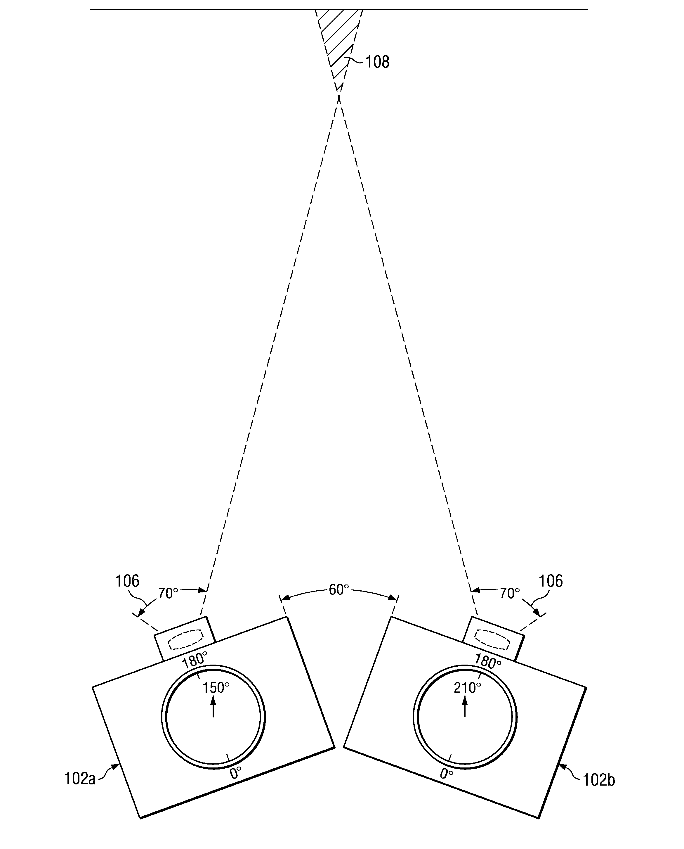
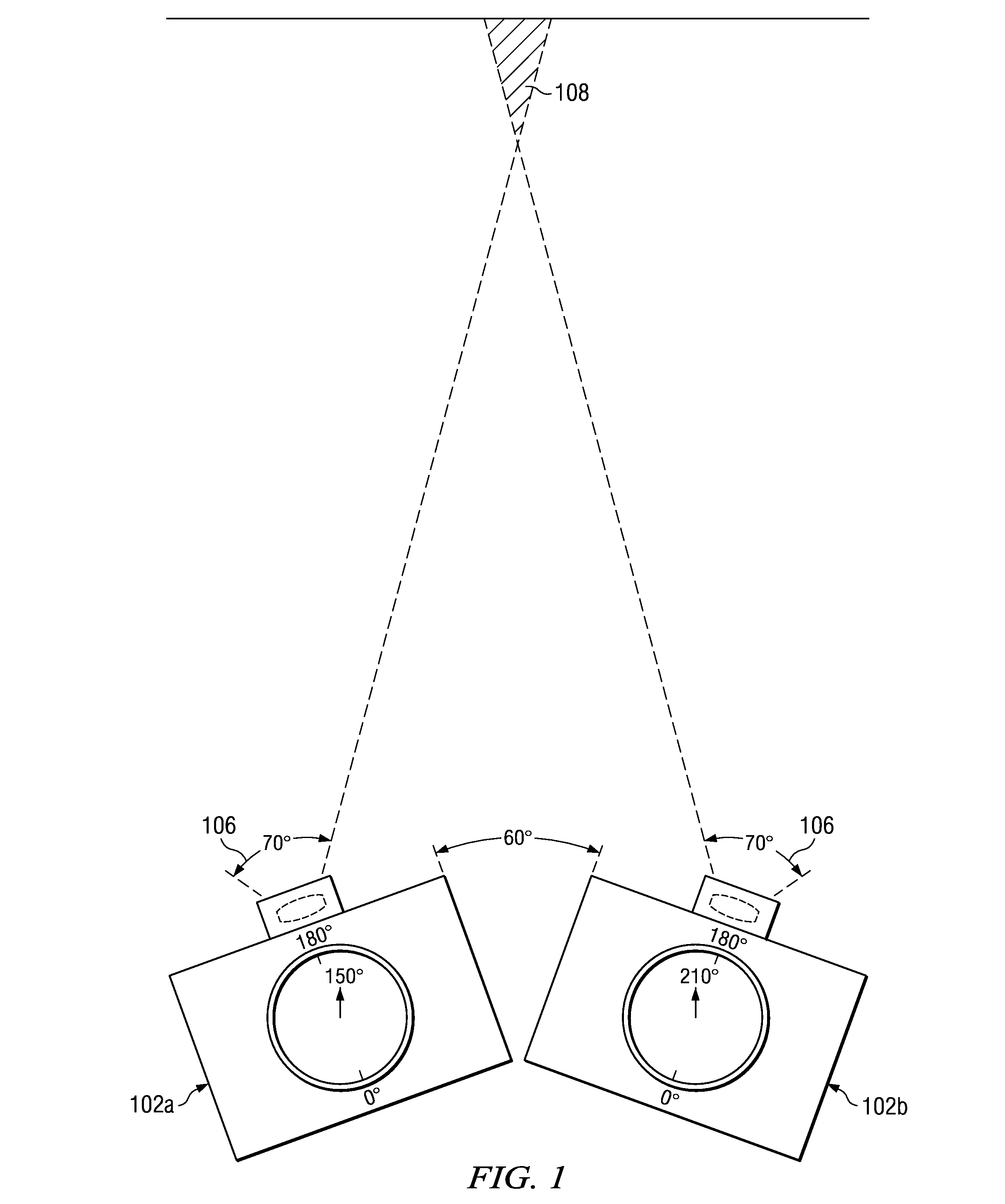
[0020]As shown in FIG. 1, camera 102A, representing camera 102 in a first position A, has a first horizontal azimuth angle corresponding to the first of a multiplicity of images to be captured to generate a horizontal panoramic image. Presume, for example, the horizontal field of view 106 of camera 102 is 70 degrees, and further presume that 10 degrees of overlap is desired between adjacent images. Azimuth angle sensor 104 comprises an electronic compass, a differential azimuth angle sensor such as a turn rate sensor, or other known azimuth angle sensor. The azimuth angle value at the time of first image capture is 150 degrees, for example, and is stored as a starting reference. As camera 102 is rotated to azimuth angle as shown in 102B, the azimuth angle value changes to 210 degrees, at which time the shutter is automatically activated, capturing the second or subsequent image which typically overlaps the prior image as shown by overlap 108.

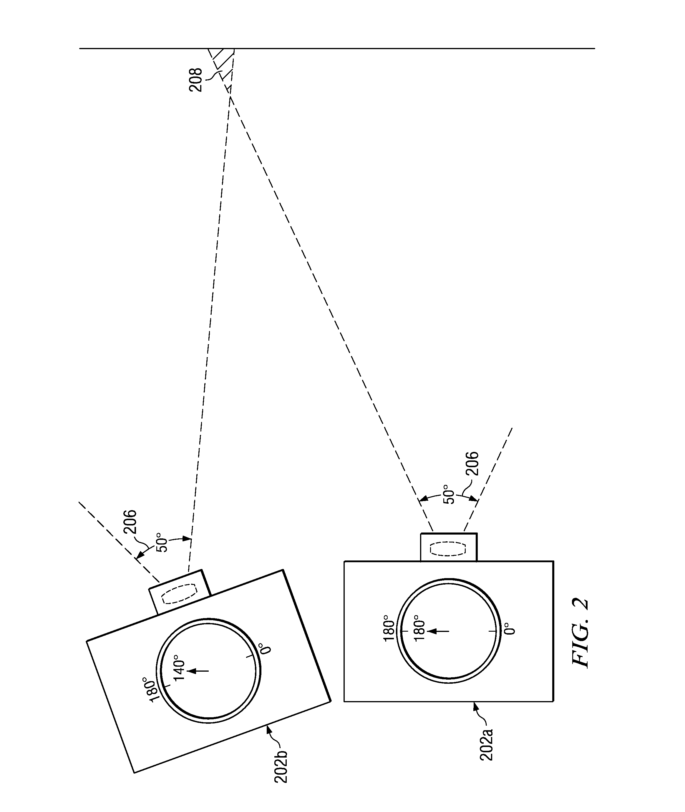
[0021]As shown in FIG. 2, camera 202A, re...


PUM


Abstract

An angle sensor 302 in a digital or film camera senses the absolute or differential azimuth angle of the camera. At the time of first image capture, the camera azimuth angle H1 is latched in storage register 304. A constant angle value K degrees is added to this stored angle H1, and the sum is then a target angle value H1+K. As the camera continues to rotate, angle value H is compared in comparator 306 to H1+K, and when substantially equal, a command is generated activating shutter 318 to capture the second image and store the current azimuth angle H2 in storage register 304. An alternative embodiment stores a reference image portion pixel data set from a reference image portion 404 of the first captured image. As the camera rotates, a new pixel data set from a sampled image portion on the opposite side of the field of view is captured every few degrees, and is compared to the stored reference image portion pixel data set. When the camera has rotated such that the sampled image portion pixel data set substantially equals the reference image portion pixel data set, a peak in correlation occurs which generates a shutter activation command to capture the next image in the sequence. At the substantially same time a new reference image portion pixel data set is stored.

Description

BACKGROUND OF THE INVENTION[0001]1. Field Of The Invention[0002]This invention relates generally to photography, and, in particular, to panoramic photography with a digital camera, by capturing multiple overlapping images which may be electronically merged to form a single image.[0003]2. Description Of The Related Art[0004]The lens system of typical film and digital cameras captures images with an aspect ratio (width to height ratio) of approximately 1.5 (3:2). For example, a frame of typical 35 mm film measures 36 mm by 24 mm (3:2 aspect ratio). Most digital cameras use image sensors having a 4:3 aspect ratio, to match the 4:3 aspect ratio of many computer monitors and televisions.[0005]Panoramic photographs generally have an aspect ratio significantly higher than 1.5. One type of panoramic camera uses a wide angle lens to capture a panoramic image on a portion of one standard film frame; for example, an image 36mm wide and 12 mm high (rather than the standard 24 mm high) on a stan...

Claims


Application Information

Patent Timeline
IPC IPC(8): H04N7/00
CPCG03B37/04
Inventor GELSOMINI, TITODAVIS, HARVEYMARSHALL, ANDREW
Owner TEXAS INSTR INC
Why Eureka
Try Eureka