Heat transfer apparatus containing a compliant fluid film interface and method therefor

a fluid film interface and heat transfer apparatus technology, applied in the direction of cooling/ventilation/heating modification, semiconductor/solid-state device details, semiconductor devices, etc., can solve the problem of poor thermal conductivity of tim, and achieve the effect of providing the needed space for thermal expansion mismatch

Inactive Publication Date: 2008-07-03
IBM CORP
View PDF16 Cites 10 Cited by
  • Summary
  • Abstract
  • Description
  • Claims
  • Application Information

AI Technical Summary

Benefits of technology

[0012]Therefore, by designing the metallic separator that isolates the fluid film from the heat source with compliance along its periphery, the needed space for thermal expansion mismatch is provided. Existence of compliance further allows minimum gap TIM as well as eliminates a paste depletion (or pumping) problem.

Problems solved by technology

The TIM generally has poor thermal conductivity.
A cooling device for a microprocessor may weigh as much as (>0.5 kg), and typically cannot be directly attached to a chip because the mechanical stresses may unfavorably strain and crack the chip.

Method used


Image

  • Heat transfer apparatus containing a compliant fluid film interface and method therefor
  • Heat transfer apparatus containing a compliant fluid film interface and method therefor
  • Heat transfer apparatus containing a compliant fluid film interface and method therefor

Examples


Embodiment Construction

[0023]Referring now to the drawings, and more particularly to FIGS. 1(a)-9, there are shown exemplary embodiments of the method and structures according to the present invention.

Exemplary Embodiment

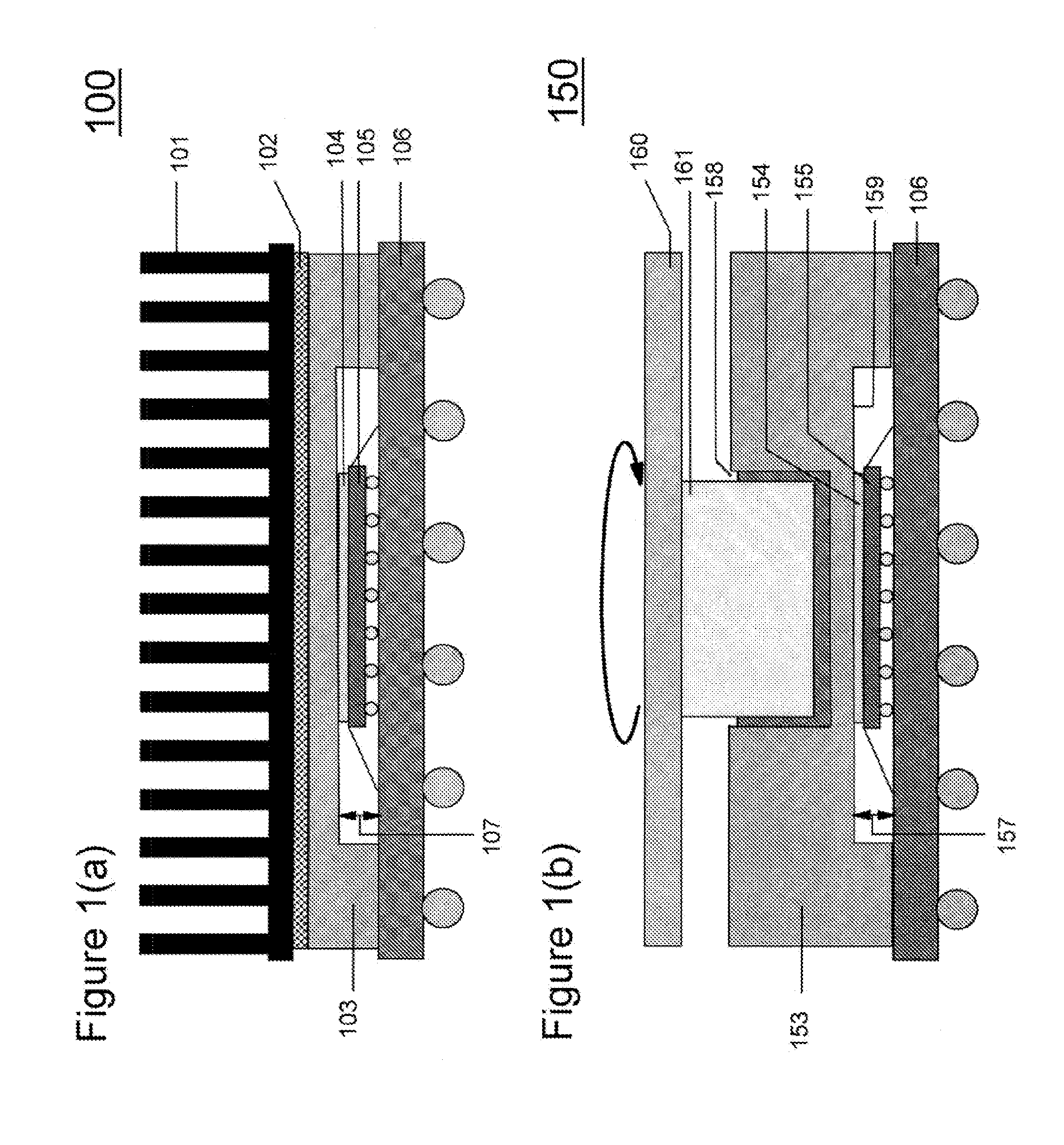
[0024]FIG. 1(a) shows a conventional structure 100 including a static heat sink 101. A thermal interface material (TIM) 102 provides heat conduction from one modular component to another, while absorbing the thermally induced variation in clearances between the components. A rigid heat spreader 103 is provided between TIM 102 and another TIM 104. TIM 104 is applied to a top surface of a die (chip) 105. “Legs” of the spreader 103 are mounted on a ceramic base 106. As shown by reference numeral 107, there is a rigid spacing between the under surface of the spreader 103 and a top surface of the ceramic base 106.

[0025]FIG. 1(b) shows a structure 150 including a novel kinetic heat sink (KHS) where a rigid heat spreader 153 supports a fluid film 158 on one side and provides a conduction path f...


PUM


Abstract

A heat transfer device (and method therefore) for transferring heat from a heat source to a heat conductor, includes a fluid film operable as a compliant interface between the heat source and the heat conductor. The heat source includes a microelectronic device.

Description

BACKGROUND OF THE INVENTION[0001]1. Field of the Invention[0002]The present invention generally relates to a method and apparatus for cooling electronic components, and more particularly to a method and apparatus for heat transfer using a compliant fluid film interface.[0003]2. Description of the Related Art[0004]Present cooling devices are configured to make contact with a computer chip through a paste-like thermal interface material (TIM). The TIM generally has poor thermal conductivity.[0005]Therefore, it is desirable to minimize the thickness of the TIM to keep the thermal resistance as low as possible. However, a finite (e.g., 100 μm) mechanical clearance is needed between the chip surface and a cooling device, to accommodate thermal expansion and contraction encountered during the power cycles of a system. A cooling device for a microprocessor may weigh as much as (>0.5 kg), and typically cannot be directly attached to a chip because the mechanical stresses may unfavorably ...

Claims


Application Information

Patent Timeline
Patent Type & Authority Applications(United States)
IPC IPC(8): H05K7/20
CPCH01L23/433H01L23/467H01L2224/16H01L2224/73253H01L2924/15311H01L2924/16152H01L2924/10253H01L2924/01322H01L2924/00H01L2924/00014H01L2924/00011H01L2224/0401
Inventor KHANNA, VIJAYESHWAR DASMCVICKER, GERARDSRI-JAYANTHA, SRI M.
Owner IBM CORP
Why Eureka
Try Eureka