Boundary microphone

a microphone and boundary technology, applied in the field of boundary microphones, can solve the problems of cavity resonance generation noise, influence of strong electromagnetic waves emitted by cellular phones, etc., and achieve the effect of preventing cavity resonance and strengthening the shield

Inactive Publication Date: 2008-07-03
AUDIO-TECHNICA
View PDF3 Cites 15 Cited by
  • Summary
  • Abstract
  • Description
  • Claims
  • Application Information

AI Technical Summary

Benefits of technology

[0019]According to the present invention, since the space in the microphone case is filled with a filler (preferably, a metallic wool material or a conductive sponge material) having electric conductivity, permeability, and elasticity in combination, the electric field in the space in the microphone case is short-circuited, so that the occurrence of cavity resonance is prevented. Also, since the number of contact locations increases, the shield is strengthened.

Problems solved by technology

It is screw-mounted at one point because screw-mounting at many points provides bad appearance.
However, in the field of microphone, as cellular phones have come into wide use in recent years, the influence of strong electromagnetic waves emitted from the cellular phone has posed a problem.
The formation of cavity resonator generates noise.

Method used


Image

  • Boundary microphone
  • Boundary microphone
  • Boundary microphone

Examples


Embodiment Construction

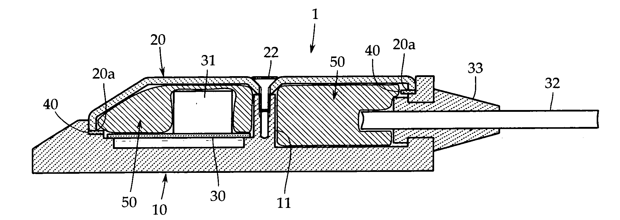
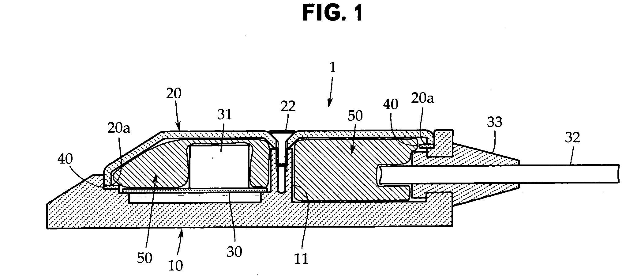
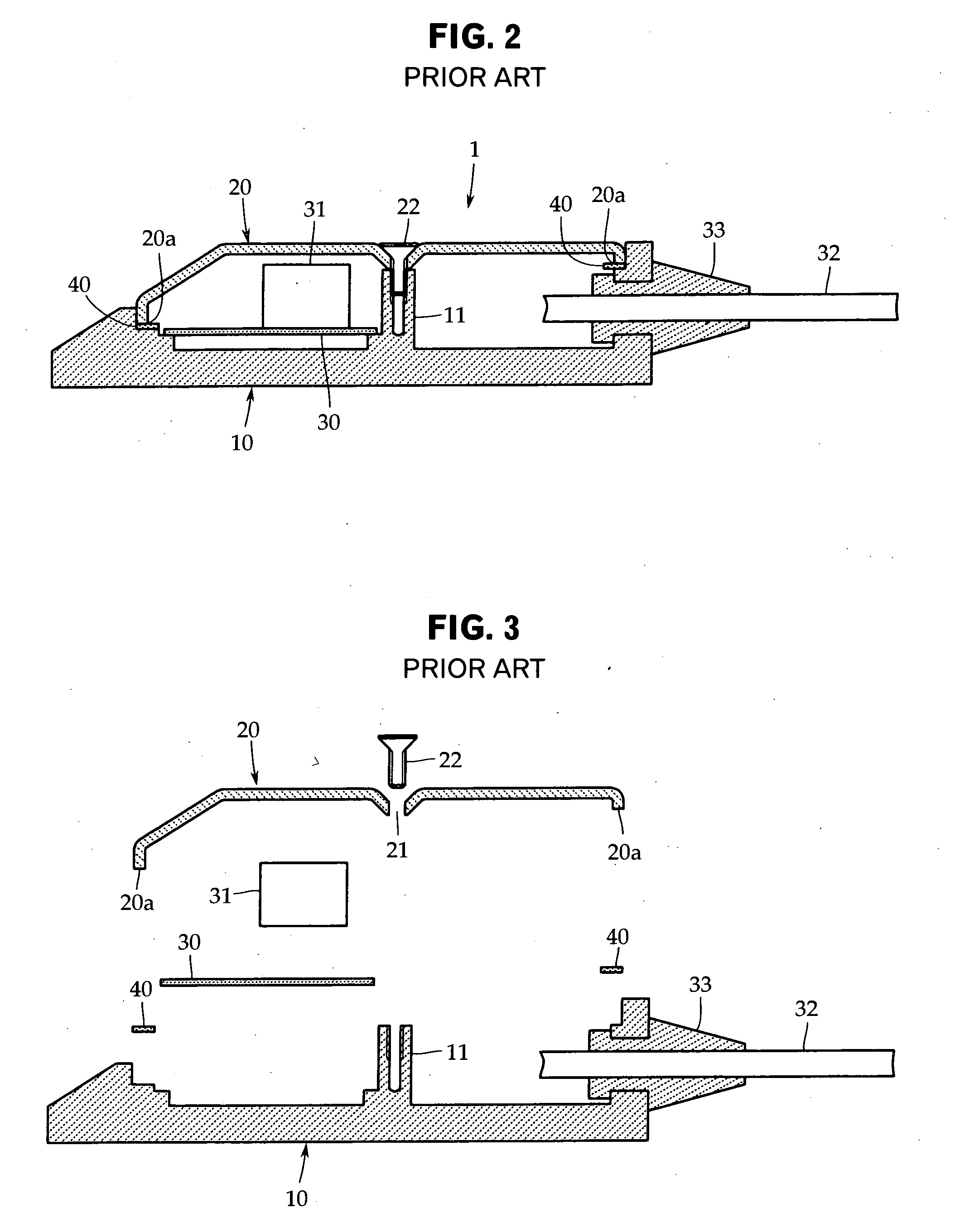
[0023]An embodiment of the present invention will now be described by reference to FIG. 1. The present invention is not limited to this embodiment. FIG. 1 is a sectional view showing an embodiment of a boundary microphone in accordance with the present invention. In the explanation of this embodiment, the same reference numerals are applied to elements that are the same as those in the conventional example explained by reference to FIGS. 2 and 3.

[0024]As shown in FIG. 1, in the boundary microphone in accordance with the present invention as well, a microphone case 1 may be formed by two elements: a flat metallic base part 10 the upper surface side of which is open, and a metallic microphone cover 20 having a large number of openings (sound wave introduction holes), which is attached to the base part 10 so as to cover the upper surface of the base part 10.

[0025]Usually, the base part 10 is formed by casting such as zinc die casting. However, as the base part 10, a press molded produc...


PUM


Abstract

Cavity resonance is prevented from being produced in a microphone case by strong electromagnetic waves of a cellular phone level in a boundary microphone provided with a flat microphone case having a relatively large internal space. In the boundary microphone including the microphone case 1 made up of a flat metallic base part 10 the upper surface of which is open and a metallic microphone cover 20 having a large number of openings (sound wave introduction holes), which is attached to the base part 10 so as to cover the upper surface of the base part 10, in which at least a microphone unit 31 and a circuit board 30 on which a predetermined electric circuit is formed are housed in the microphone case 1, the space in the microphone case 1 is filled with a filler (for example, a metallic wool material or a conductive sponge material) 50 having electric conductivity, permeability, and elasticity in combination.

Description

TECHNICAL FIELD[0001]The present invention relates to a boundary microphone and, more particularly, to a technique for preventing the generation of noise caused by extraneous electromagnetic waves.BACKGROUND ART[0002]A boundary microphone (on-surface sound pickup microphone) is also called a surface mount microphone because it is used by being installed on a table or floor surface in a TV studio, a conference room, or the like. As described in Patent Document 1 (Japanese Utility Model Registration No. 2515812), the boundary microphone uses a flat microphone case. One example thereof is explained by reference to the sectional view of FIG. 2 and the exploded sectional view of FIG. 3.[0003]Referring to FIGS. 2 and 3, a microphone case 1 used for a boundary microphone is basically made up of two elements: a flat metallic base part 10 the upper surface side of which is open, and a metallic microphone cover 20 having a large number of openings (sound wave introduction holes), which is att...

Claims


Application Information

Patent Timeline
Patent Type & Authority Applications(United States)
IPC IPC(8): H04R11/04
CPCH04R1/342H04R1/04
Inventor AKINO, HIROSHIOKITA, SHIOTOYOSHINO, SATOSHI
Owner AUDIO-TECHNICA
Why Eureka
Try Eureka