Device and method for mounting an object on a bone

Inactive Publication Date: 2008-07-03
EVERGREEN ORTHOPEDIC RES LAB LLC
View PDF23 Cites 50 Cited by
  • Summary
  • Abstract
  • Description
  • Claims
  • Application Information

AI Technical Summary

Benefits of technology

[0031]FIG. 15 is a further simplified view of the portion of a leg shown

Problems solved by technology

While an estimate can be initially made of the size of a bone, time may be wasted if a mounting device of the wrong size is chosen initially and must be replaced.
Adjustment of some previously available devices to securely support an object such as a part of a navigation system has required separate operations of first drilling and thereafter tapping

Method used


Image

  • Device and method for mounting an object on a bone
  • Device and method for mounting an object on a bone
  • Device and method for mounting an object on a bone

Examples


Embodiment Construction

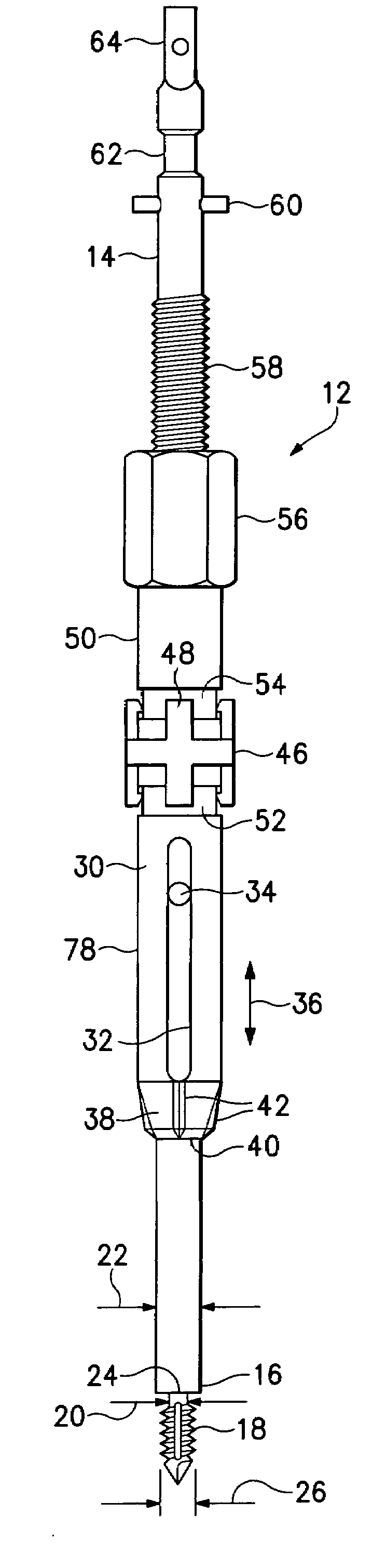
[0032]Referring now to the drawings which form a part of the disclosure herein, an anchoring device 12, shown in its entirety in FIG. 1, includes a central shaft 14. At a distal end portion 16 of the shaft 14 a threaded tip 18 extends axially. The threaded tip 18 may be of a self-drilling, self-tapping configuration, but need not necessarily be so. The threaded tip 18 may include a central portion with a diameter 20 significantly smaller than a diameter 22 of the central shaft 14, and the central shaft 14 thus may define a shoulder 24. A helical thread defined on the threaded tip 18 may extend radially to a diameter 26 which also should be at least slightly less than the diameter 22 for best performance.

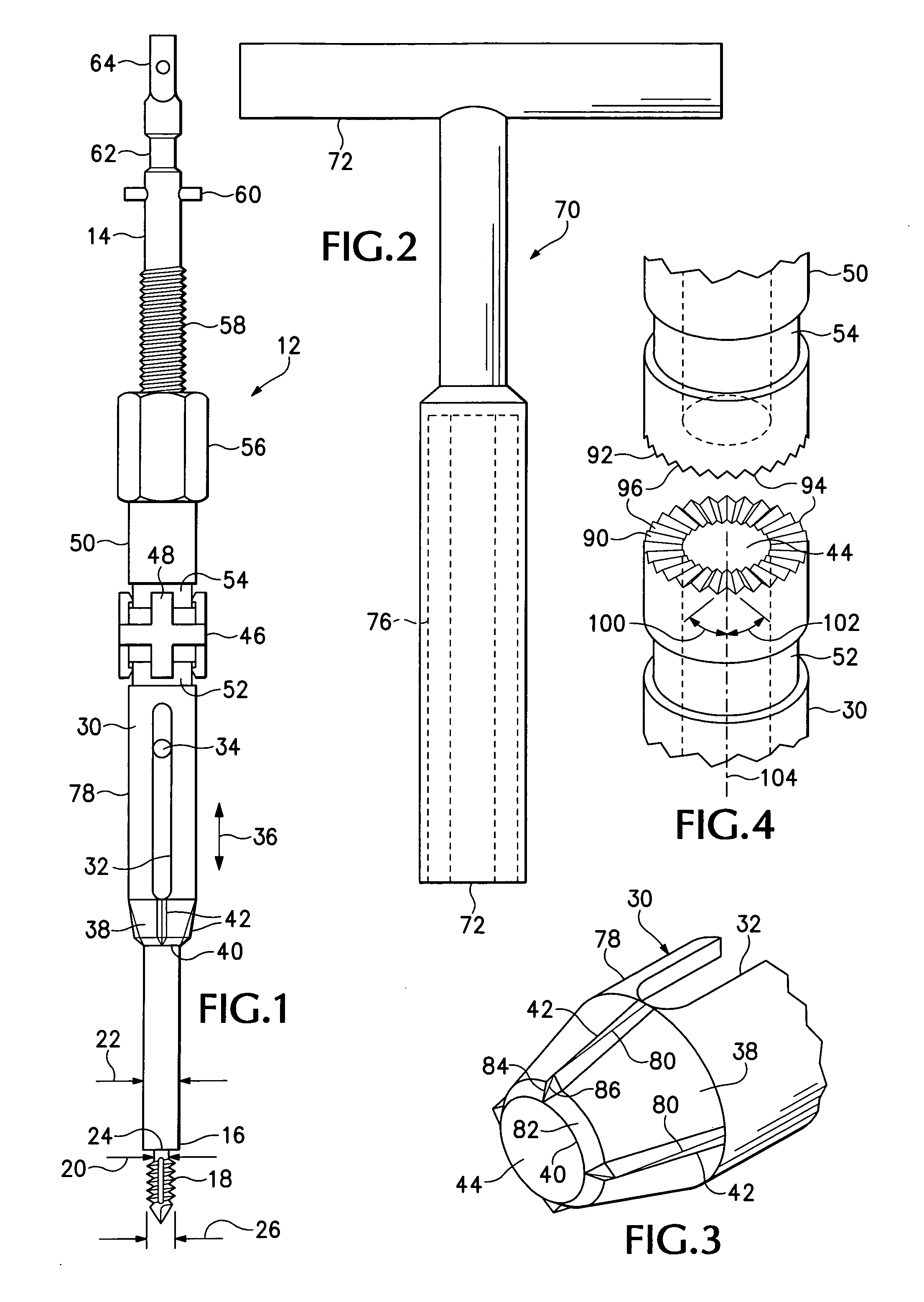
[0033]A bone-engaging member in the form of a tubular sleeve 30 is located on the central shaft 14 with a sliding fit. A slot 32 extends radially and longitudinally of the sleeve 30 on at least one side thereof, and a pin 34 mounted in and extending radially from the shaft 14 is enga...


PUM


Abstract

A device for removable attachment to a bone of a living patient, useful as a mounting support for a trackable part of a computerized surgical navigation system and a method for attaching an object removably to a bone of a living patient. A shaft having a self drilling, self-tapping screw tip can be inserted transversely of the bone and securely screwed into the cortex. A screw drives a sharp-edged sleeve along the shaft to engage the near cortex. A stepping mechanism allows incremental angular movement of a portion of an adjustment mechanism and indicates when the sleeve is securely engaged by resisting further tightening.

Description

BACKGROUND OF THE INVENTION[0001]The present invention relates to releasably attaching an object to a bone in a living patient, and relates particularly to a device for fastening an object such as a component of a computerized surgical navigation system stably to a large bone such as a femur.[0002]In surgical procedures involving articulated skeletal bone joints, such as knee replacement procedures, it is often helpful to use computer-aided navigation, based on infrared or electromagnetic imaging systems, to locate bones or parts of bones correctly with respect to each other during the procedure. In order to establish and monitor the position of a large bone as a reference for such computer-aided navigation, a reference device must be securely and stably, but removably, mounted on the large bone.[0003]Attachment of objects to bones has been addressed by the prior art, as disclosed, for example, by Glossop U.S. Pat. No. 6,203,543 and Sasso U.S. Patent Application Publication No. US20...

Claims


Application Information

Patent Timeline
IPC IPC(8): A61B17/00A61B17/56A61B17/58
CPCA61B17/86A61B17/8635A61B2017/8655A61B2019/5483A61B2019/305A61B2019/5416A61B2019/301A61B2090/3983A61B2090/3916A61B2090/031A61B2090/035A61B2090/3991
Inventor MCALLISTER, CRAIG M.JACOBSON, STEVEN
Owner EVERGREEN ORTHOPEDIC RES LAB LLC
Why Eureka
Try Eureka