Passive restraint for prevention of uncontrolled motion

Inactive Publication Date: 2008-07-10
GRAY MFG
View PDF5 Cites 50 Cited by
  • Summary
  • Abstract
  • Description
  • Claims
  • Application Information

AI Technical Summary

Benefits of technology

[0008]The present invention generally provides a passive dynamic restraint arrangement for selectively restricting flow of pressurized fluid within a cylinder through passages of a floating piston head to thereby restrain sudden relative movement between the cylinder and a piston rod having the piston floating thereon.
[0010]During normal gradual extension and retraction of the pneumatic lift cylinder, fluid flows freely between the chambers of the restraint device, to prevent interference with the normal operation of the pneumatic cylinder. However, if the pneumatic cylinder begins to suddenly extend, the passive restraint device will activate to limit the rate of extension of the pneumatic cylinder. The pneumatic cylinder may still extend; however, it can be designed such that vertical movement is limited to occur within current applicable standards. The restraint mechanism is configured in such a manner that it can function at any position along the stroke of the pneumatic cylinder.

Problems solved by technology

However, if the pneumatic cylinder begins to suddenly extend, the passive restraint device will activate to limit the rate of extension of the pneumatic cylinder.
The pneumatic cylinder may still extend; however, it can be designed such that vertical movement is limited to occur within current applicable standards.
However, when the piston engages the flange, flow through the piston passages is highly restricted.

Method used


Image

  • Passive restraint for prevention of uncontrolled motion
  • Passive restraint for prevention of uncontrolled motion
  • Passive restraint for prevention of uncontrolled motion

Examples


Embodiment Construction

[0020]As required, detailed embodiments of the present invention are disclosed herein; however, it is to be understood that the disclosed embodiments are merely exemplary of the invention, which may be embodied in various forms. Therefore, specific structural and functional details disclosed herein are not to be interpreted as limiting, but merely as a basis for the claims and as a representative basis for teaching one skilled in the art to variously employ the present invention in virtually any appropriately detailed structure.

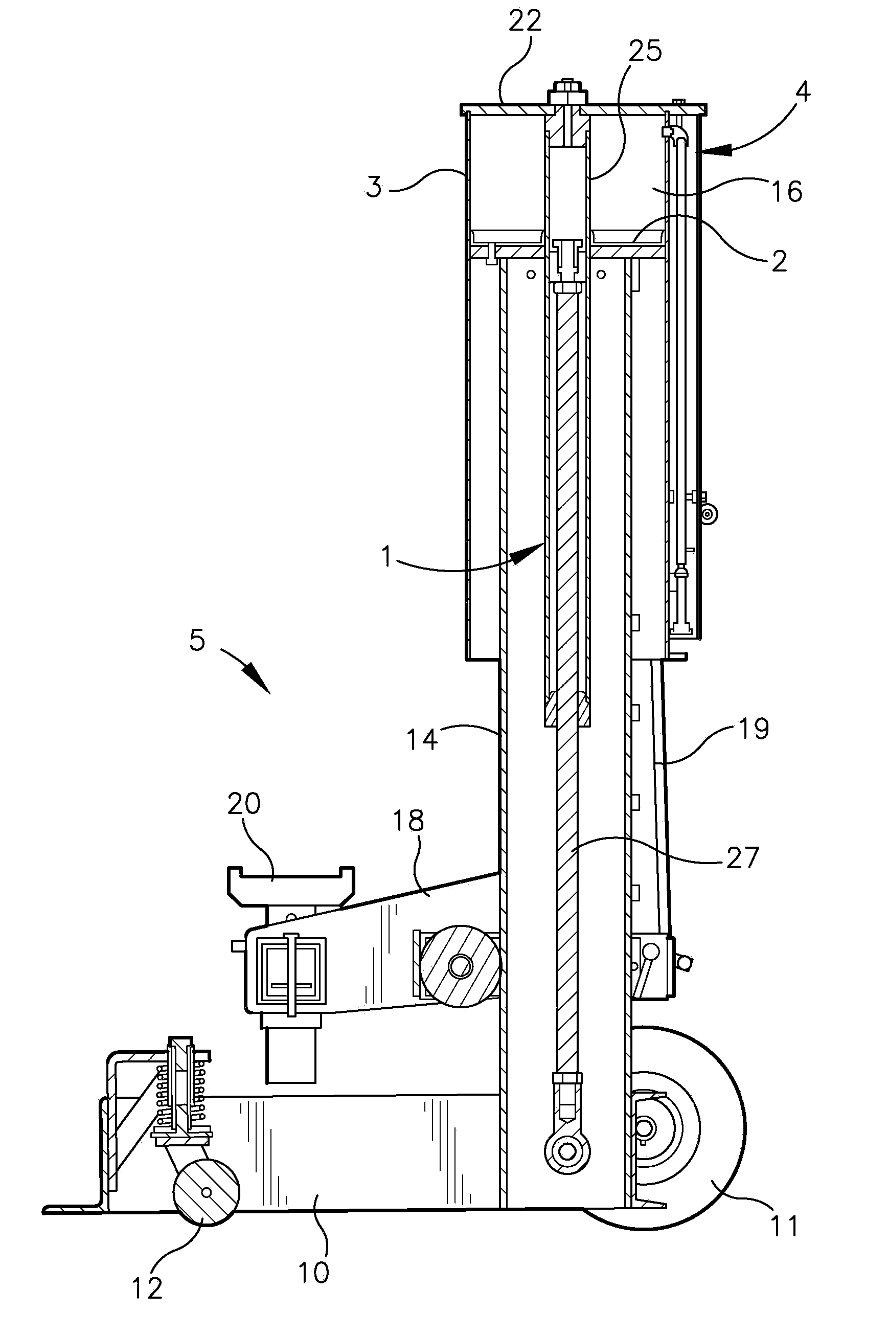
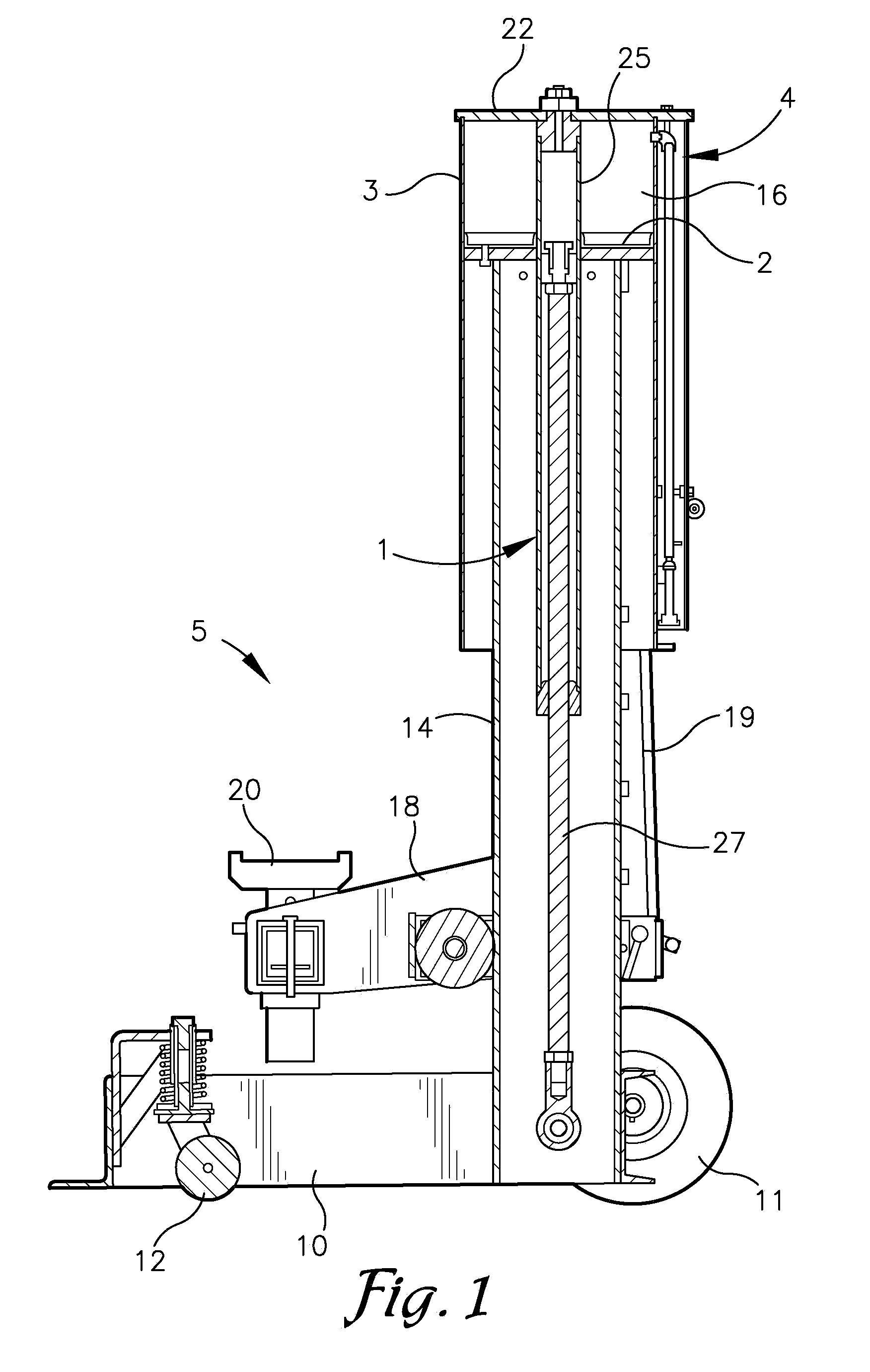
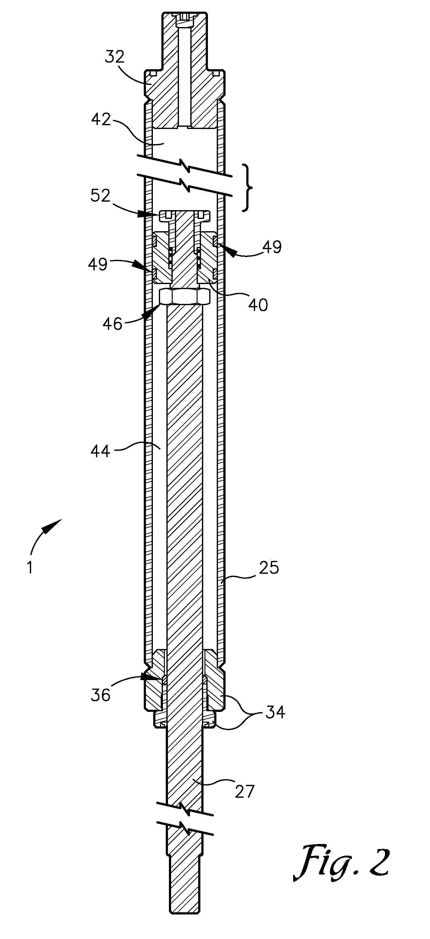
[0021]Referring to the drawings in more detail, the reference numeral 1 generally designates a passive restraint apparatus for prevention of uncontrolled motion which is an embodiment of the present invention. The restraint or strut apparatus 1 functions to allow gradual movement between two members, such as a piston 2 and a cylinder 3 of a pneumatic linear motor 4, but which retards sudden movement therebetween. In the illustrated embodiment, the pneumatic m...


PUM


Abstract

A passive energy absorbing strut for dynamic restraint includes a hydraulic cylinder, a hydraulic piston rod extending from the cylinder, a rod stem on the end of the rod and having a flange and a stop at opposite ends, a floating piston member sleeved on the stem between the flange and the stop, the piston member having fluid passages therethrough, and a piston spring urging the piston member away from the flange. The flange is sized to restrict the piston passages when the piston member engages the flange. The piston member is driven toward the flange in reaction to initiation of sudden extension of the strut, thereby restricting the piston passages and the flow of hydraulic fluid therethrough. The strut is connected between a piston and cylinder of a pneumatic vehicle end lift to damp sudden extension of the lift in response to loss of the load.

Description

CROSS-REFERENCE TO RELATED APPLICATION[0001]This application claims priority under 35 U.S.C. 119(e) and 37 C.F.R. 1.78(a)(4) based upon copending U.S. Provisional Application Ser. No. 60 / 879,395 for ENERGY ABSORBING STRUT FOR DYNAMIC RESTRAINT, filed Jan. 9, 2007, which is incorporated herein by reference.BACKGROUND OF THE INVENTION[0002]The present invention is generally directed to pneumatic vehicle end lifts and, more particularly, to such an end lift incorporating an internal energy absorbing strut for dynamic restraint to resist sudden or uncontrolled extension of the lift in response to accidental loss of the load.[0003]The need to lift vehicles for service work is well established and has been implemented by both permanent and mobile lift devices. Upright mobile end lift devices for engaging a bumper of a vehicle to lift the end of the vehicle for service are well known. A particular problem with pneumatic end lifts is that a sudden loss of the load can cause a sudden expansi...

Claims


Application Information

Patent Timeline
IPC IPC(8): B66F11/00F16F9/10
CPCB66F5/04B66F7/04F16F9/512F16F9/06B66F17/00
Inventor GRAY, JOSEPH L.MCKEE, RALPH S.
Owner GRAY MFG
Why Eureka
Try Eureka