Endoscopic Capsule

a magnetic resonance and endoscope technology, applied in waveguide devices, instruments, reradiation, etc., can solve the problems of significant technical expenditure, unfavorable resonator application length, and inability to achieve tuning

Inactive Publication Date: 2008-07-10
SIEMENS HEALTHCARE GMBH
View PDF14 Cites 97 Cited by
  • Summary
  • Abstract
  • Description
  • Claims
  • Application Information

AI Technical Summary

Benefits of technology

[0023]In a further embodiment, the conductor element is fashioned as a torus. Dielectrics are arranged between the layers. In this case the layer ends of a layer are respectively separated from one another by a gap as viewed in the extension direction. The gaps are not all arranged at the same point as viewed in the extension direction. The gaps of layers immediately adjacent to one another are advantageously offset along the extension direction by an angle that is slightly less than 180°.

Problems solved by technology

As results from a back calculation, the length of a λ / 2 rod given a magnetic resonance system with a basic magnetic field of 1.5 T is thus approximately 2.5 m. However, such lengths are unrealistic for resonators for magnetic resonance applications.
For resonators for magnetic resonance applications, without further measures it is therefore not possible to achieve the tuning to the Larmor frequency only by dimensioning of the conductor element.
However, these procedures have a significant technical expenditure associated therewith and moreover represent a safety risk for a patient who is examined in the magnetic resonance system.
In practice these measures are therefore not ever used in magnetic resonance systems.
However, in practice the use of a radio-frequency strand brings no advantages.
However, without further measures the use of multi-layer conductors as conductor elements does not lead to the expected reduction of the effective resistance.
More precise examinations have shown that the problem is due to the optimal distribution of the resonance current to the individual layers of the multi-layer conductor after a transition from a solid conductor or an external circuit to the multi-layer conductor ensuing only when this is ensured by corresponding design of the multi-layer conductor or the external circuit.
Moreover, slight inhomogeneities of the multi-layer conductor already lead to a significant reduction of the achievable resistance reduction.
The use of multi-layer conductors in resonators for magnetic resonance applications has conventionally been considered to be unreasonable in practice.

Method used


Image

  • Endoscopic Capsule
  • Endoscopic Capsule
  • Endoscopic Capsule

Examples


Embodiment Construction

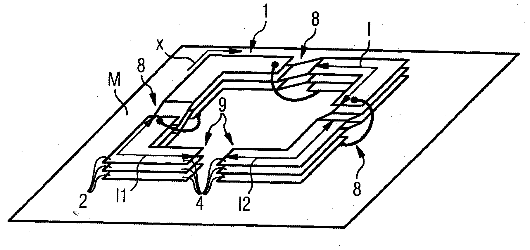
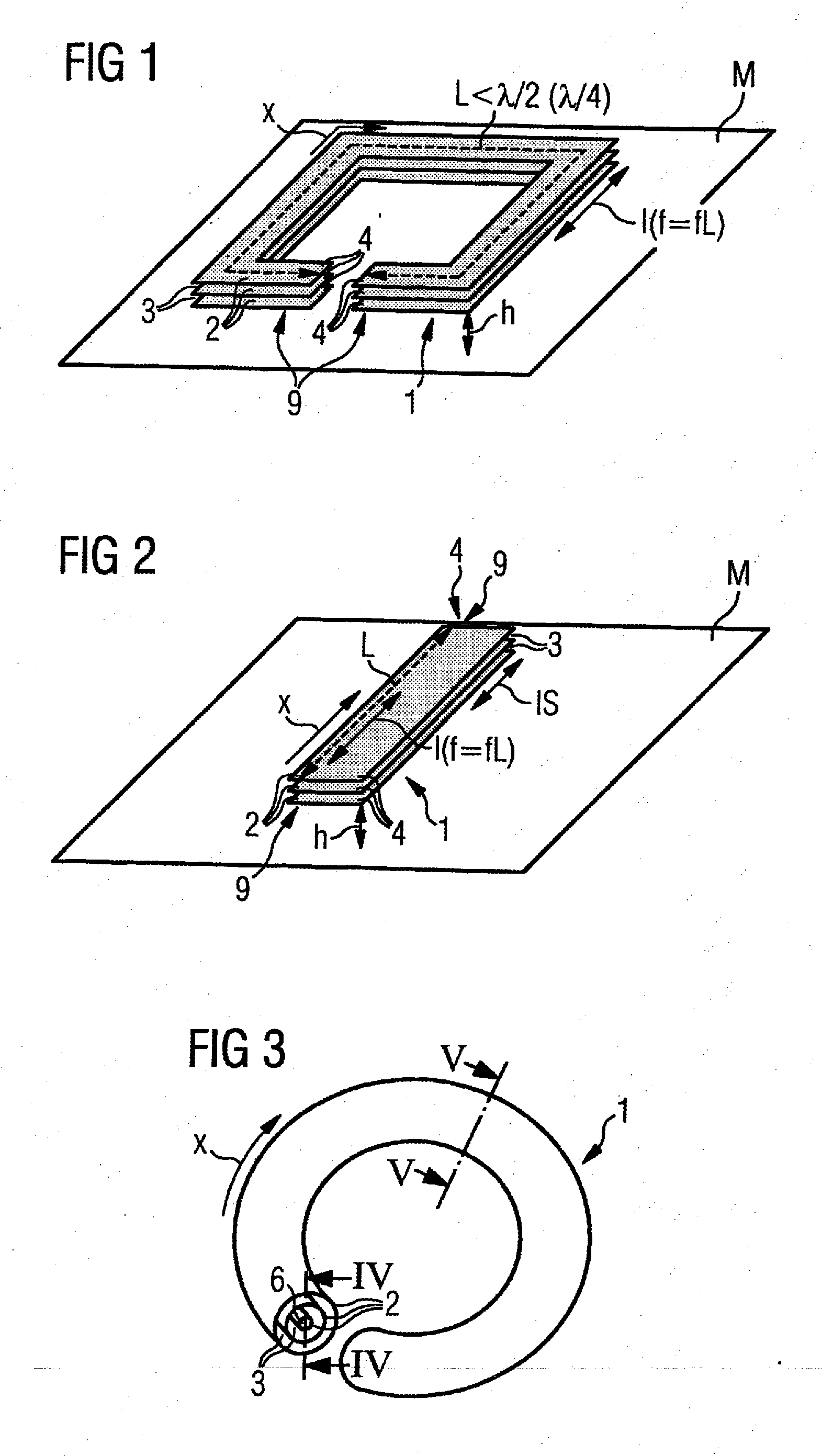
[0030]According to FIGS. 1 through 3, a resonator for magnetic resonance applications comprises a conductor element 1 that extends in an extension direction x. Given operation of the conductor element 1 a resonant current I oscillates with a resonance frequency f in the extension direction x in the conductor element 1.

[0031]Given magnetic resonance applications the resonance frequency f corresponds with the Larmor frequency fL of a magnetic resonance system. The conductor element 1 therefore extends over a total length L that is significantly smaller than half of the wavelength λ corresponding with the resonance frequency f. For the most part the total length L is even smaller than a quarter of the wavelength λ. Nevertheless, the conductor element 1 is tuned to the resonance frequency f. Details in this regard will be explained further.

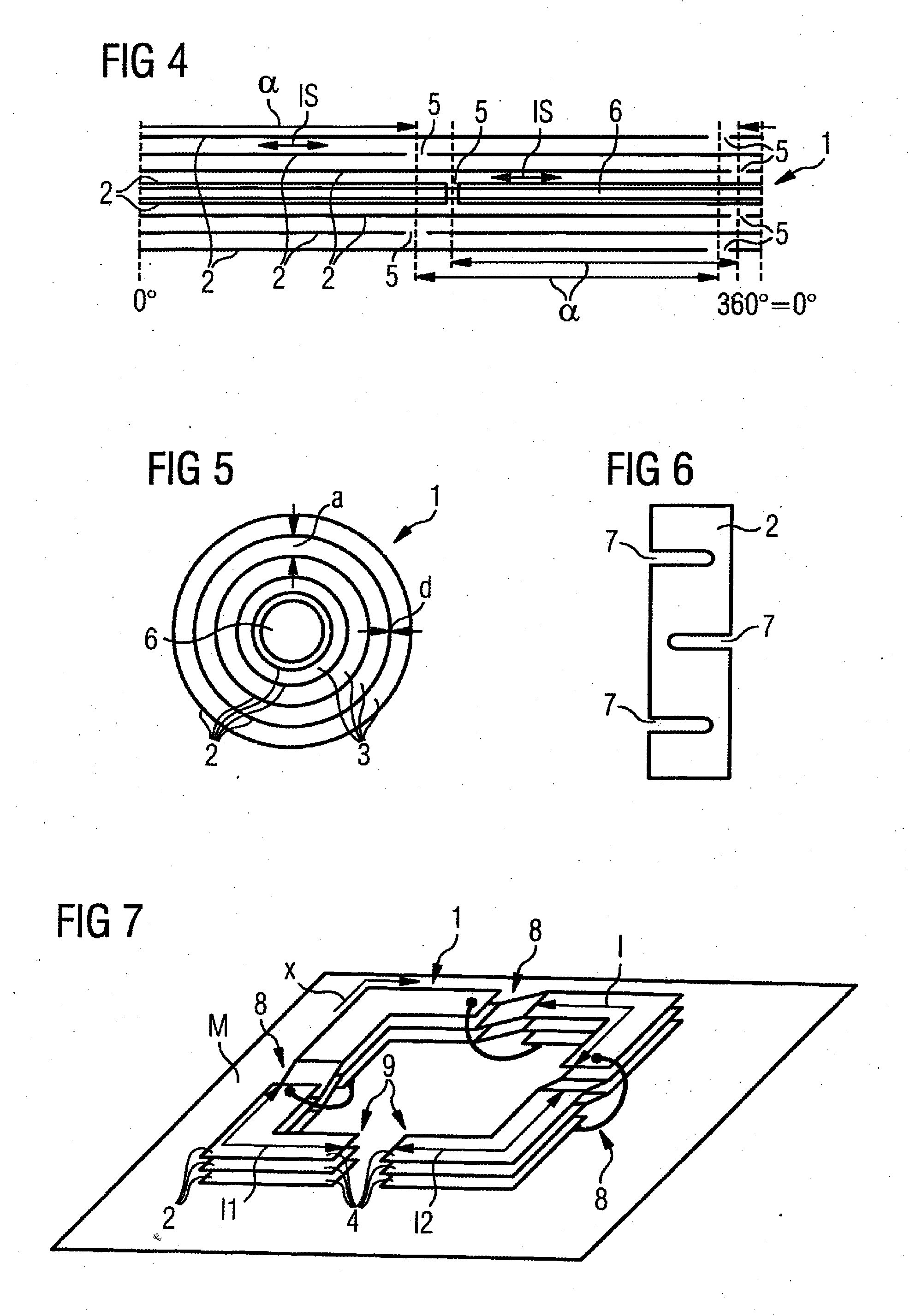
[0032]The conductor element 1 is fashioned as a multi-layer conductor. It thus comprises a plurality of electrically-conductive layers 2 that are ele...


PUM


Abstract

A resonator for magnetic resonance applications has a conductor element proceeding in an extension direction, that operates with a resonance current at a resonance frequency oscillating therein in the extension direction. The conductor element is tuned to the resonance frequency and has an overall length in the extension direction that is smaller than half of the wavelength of the resonance frequency. The conductor element is a multi-layer conductor with layers that are electrically insulated from each other that, in said extension direction, have layer ends that are capacitively coupled with each other. During operation of the conductor element at the resonance frequency, respective layer currents flow in the layers in the extension direction that are substantially equal in magnitude.

Description

BACKGROUND OF THE INVENTION[0001]1. Field of the Invention[0002]The present invention concerns a resonator for magnetic resonance applications of the type having a conductor element extending in an extension direction.[0003]2. Description of the Prior Art[0004]Resonators of the above type are generally known.[0005]Like many other resonators, resonators for magnetic resonance applications have a conductor element that extends in an extension direction. Given operation of the conductor element with a resonance frequency, a resonance current oscillates in the extension direction in the conductor element. The resonance current is particularly high when the conductor element is tuned to the resonance frequency.[0006]In magnetic resonance applications the Larmor frequency with which a particular magnetic resonance system is operated depends on the strength of the basic magnetic field of the magnetic resonance system and on the element whose excited spin should be detected. For example, fo...

Claims


Application Information

Patent Timeline
Patent Type & Authority Applications(United States)
IPC IPC(8): H01P7/08
CPCG01R33/3642G01R33/345
Inventor SCHNELL, WILFRIEDVESTER, MARKUS
Owner SIEMENS HEALTHCARE GMBH
Why Eureka
Try Eureka