

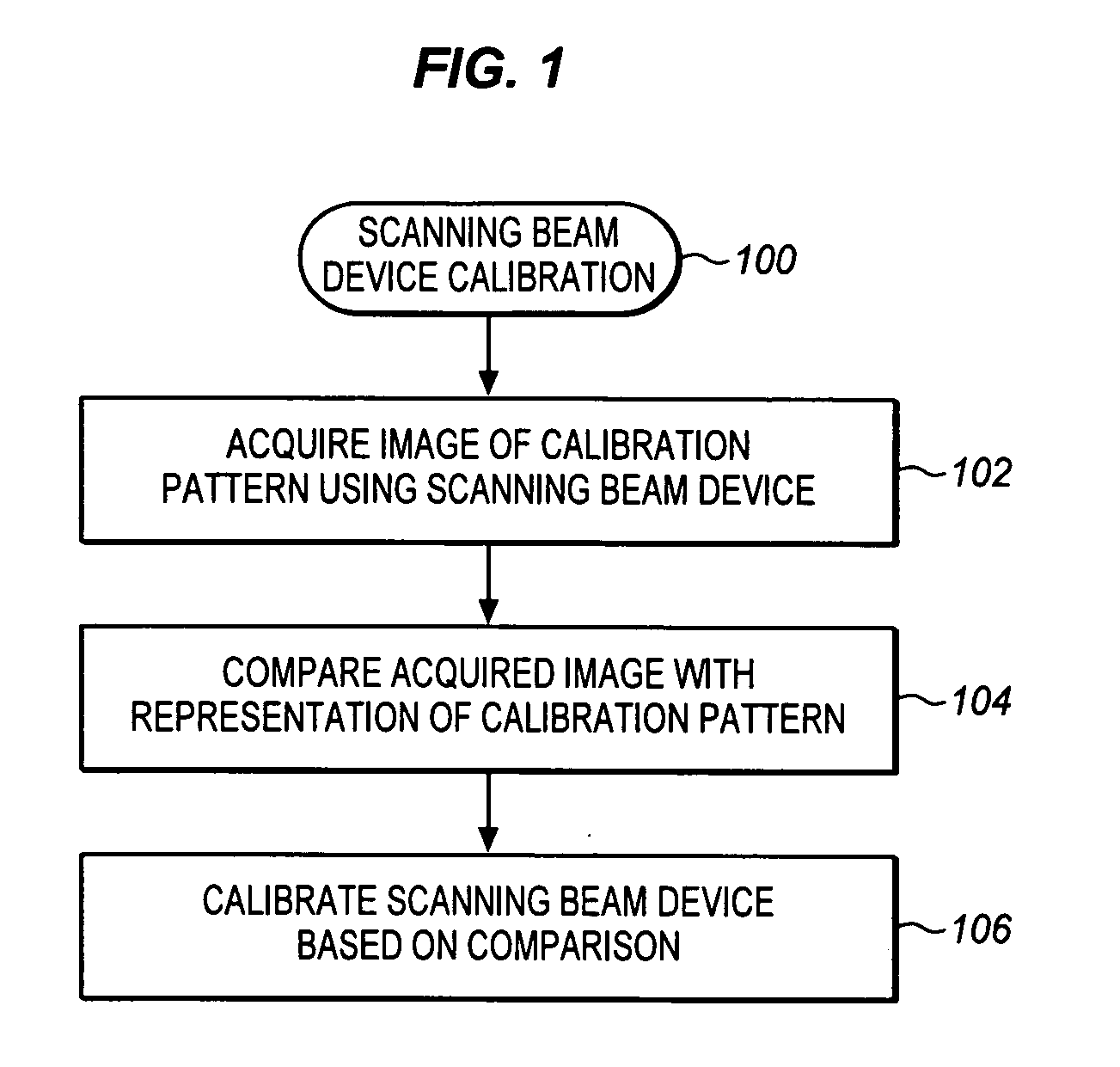
Scanning beam device calibration
a scanning beam and calibration technology, applied in the field of scanning beam devices, can solve the problems of limiting the accuracy of such estimates and adding distortion to the generated imag
- Summary
- Abstract
- Description
- Claims
- Application Information
AI Technical Summary
Problems solved by technology
Method used
Image

Examples
Embodiment Construction
[0022]In the following description, numerous specific details are set forth. However, it is understood that embodiments of the invention may be practiced without these specific details. In other instances, well-known circuits, structures and techniques have not been shown in detail in order not to obscure the understanding of this description.
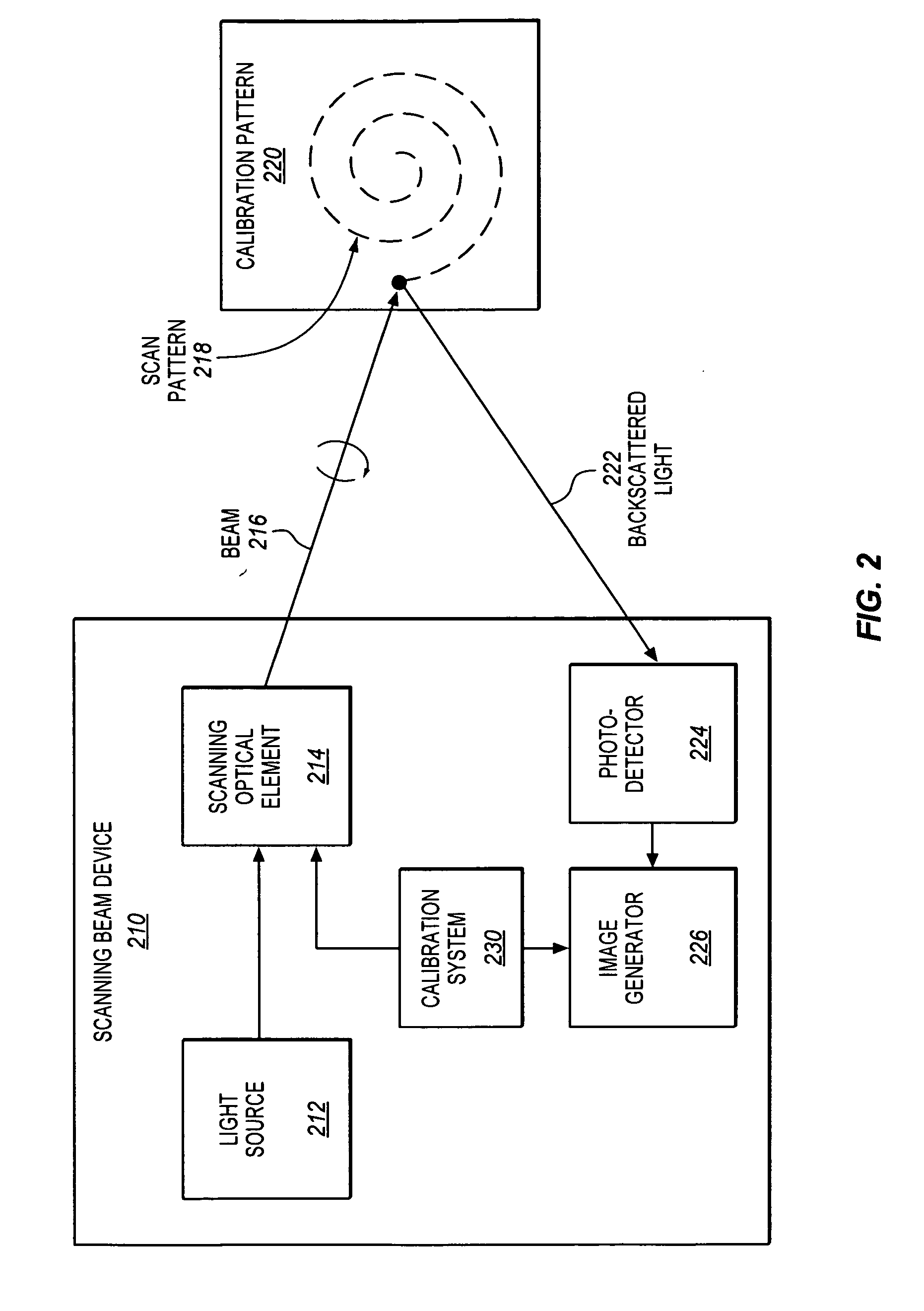
[0023]United States Patent Application 20060072843 discloses remapping methods to reduce distortion in images. As disclosed therein, a photosensitive position sensor may be used to actively capture a position of a scanning illumination spot during a scan pattern. However, the use of such a photosensitive position sensor may potentially have certain drawbacks. For one thing, the photosensitive position sensors tend to be expensive. Furthermore, the photosensitive position sensors tend to be limited in size. This may tend to restrict the field of view that may be calibrated. Yet another potential drawback is that the photosensitive position senso...
PUM
 Abstract
Description
Claims
Application Information