Flash photolysis system

a technology of flash photolysis and laser, which is applied in the field of spectroscopy, can solve the problems of system including such lasers, and bulky and expensive lasers

Inactive Publication Date: 2008-07-10
GUSEV ALEX
View PDF2 Cites 11 Cited by
  • Summary
  • Abstract
  • Description
  • Claims
  • Application Information

AI Technical Summary

Benefits of technology

[0010]In one embodiment the system for flash photolysis comprises a radiation transparent compartment for receiving a chemical sample to be analyzed; a first source of light radiation; optical means for channeling light from the first source through a chemical sample in the compartment; a second source of light radiation for directing short flash pulses of light radiation into the chemical sample in the compartment to initiate a chemical change in the sample; and means for measuring the change in absorption of the light radiation by the sample during the chemical changes in absorption of the light radiation by the sample during the chemical changes.
[0011]In another embodiment, the system for flash photolysis comprises a radiation transparent compartment for receiving a chemical sample to be analyzed; a first source of light radiation; optical means for channeling light from the first source through a chemical sample in the compartment; a second source of light radiation for directing short flash pulses of light radiation into the chemical sample in the compartment to initiate a chemical change in the sample; a second optical means for channeling light; and means for measuring the change in absorption of the light radiation by the sample during the chemical changes in absorption of the light radiation by the sample during the chemical changes, wherein said second optical means for channeling light directions

Problems solved by technology

Such lasers are bulky and expensive.
Systems including such lasers are bulky and expensiv

Method used


Image

  • Flash photolysis system
  • Flash photolysis system

Examples


Embodiment Construction

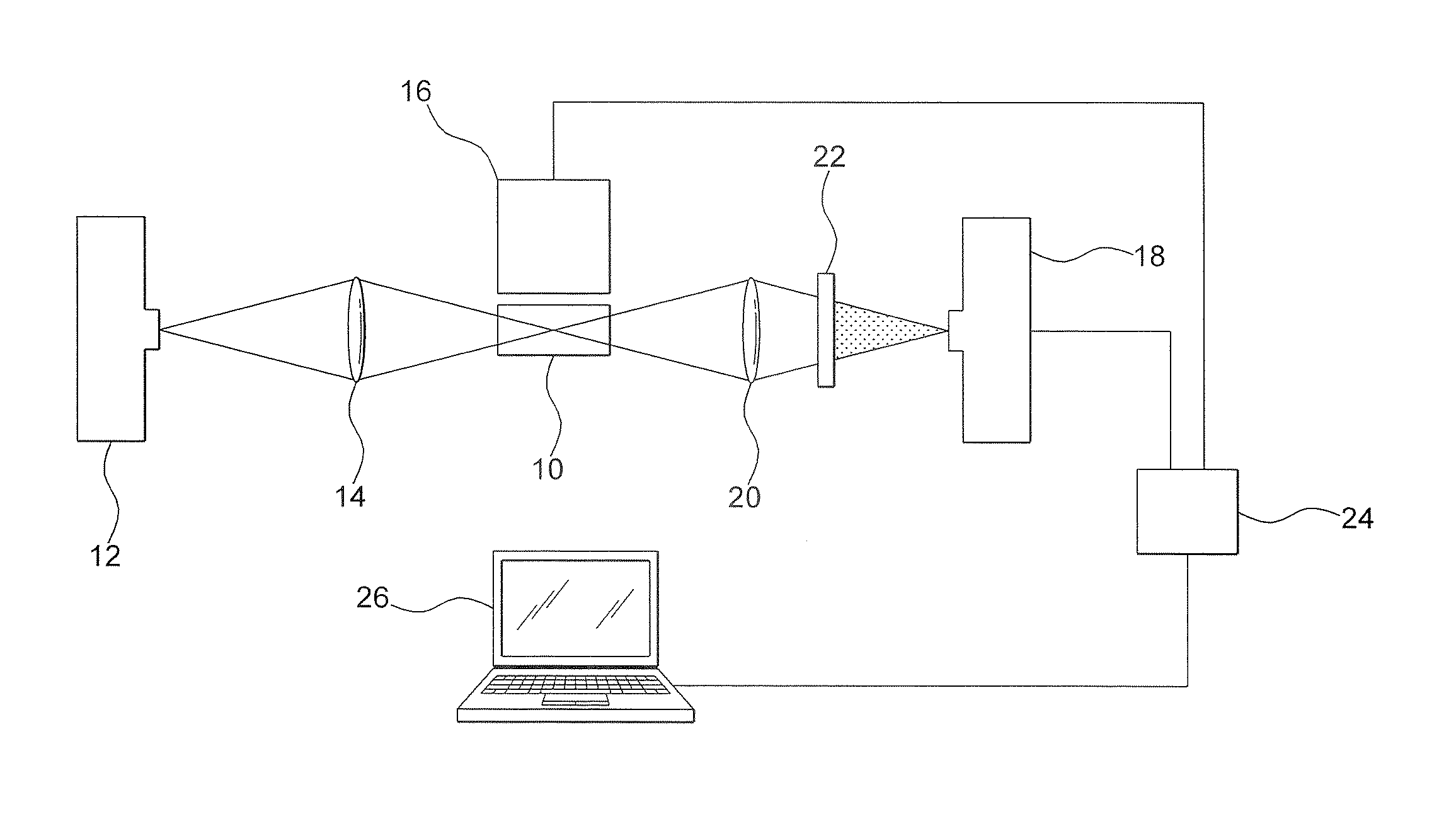
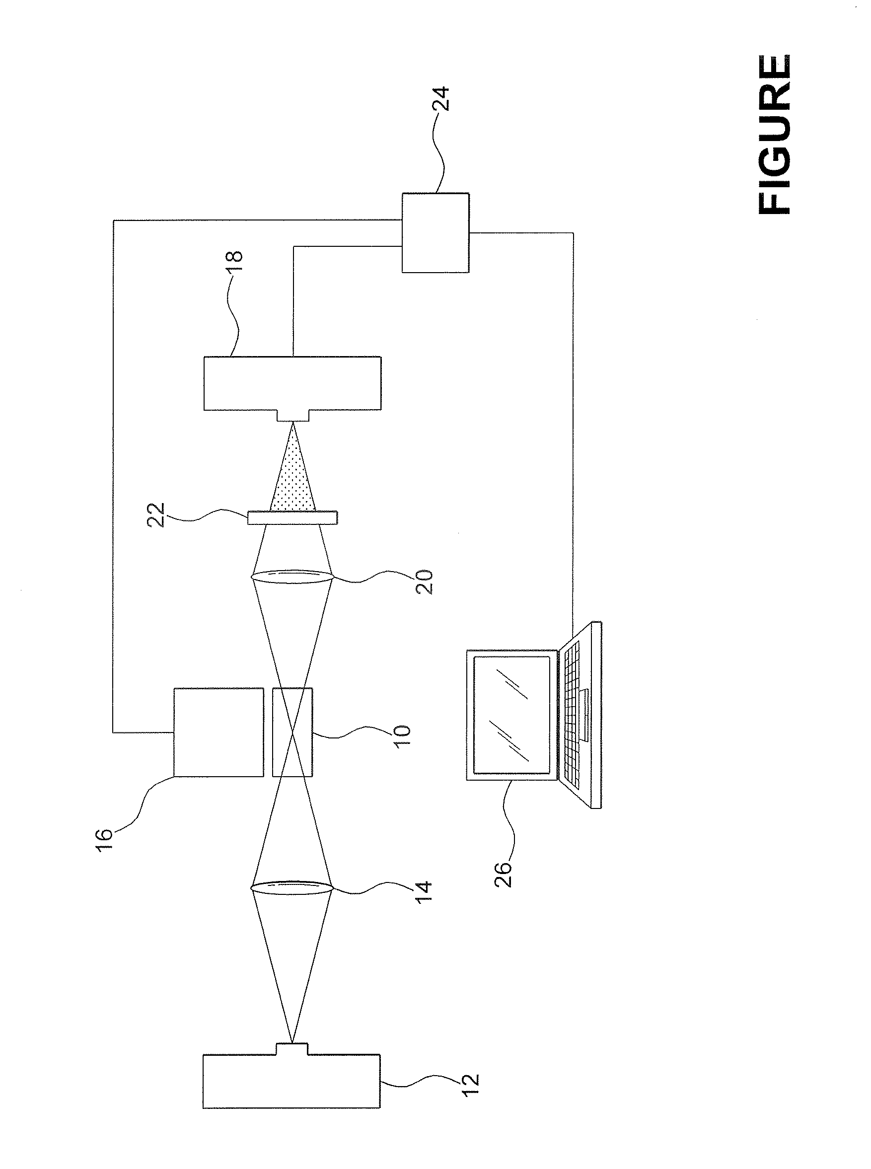
[0014]Referring to the drawing, there is illustrated an educational grade flash photolysis spectrometer which includes a compartment 10 for retaining a sample of a chemical to be analyzed. More specifically, a cuvette for retaining the chemical sample to be investigated is disposed within the compartment 10. The cuvette is typically 2 cm. in length and is transparent to the radiation used to excite the chemicals being investigated.

[0015]A first light source 12 is disposed to emit a probe source of white light electromagnetic radiation along a path through compartment 10 and the chemical being investigated. The white light radiation produced by the first light source 12 is caused to travel through the chemical sample holding cuvette by passing the radiation through a collective objective lens 14 disposed therebetween. It is understood that the first light source 12 may be any commercially available light source such as a light emitting diode (LED) or a Xe flash lamp, for example.

[001...


PUM


Abstract

A spectrometer capable of flash photolysis useful in the study of chemistry is disclosed, the spectrometer comprises a compartment for receiving a chemical sample; a first light source; a collective objective lens for directing light radiation emitted from the first light source through the chemical sample in the compartment; a second light source for directing a short flash pulse of light radiation into the chemical sample in the compartment; and a means for measuring the change in absorption having an input for receiving the light radiation emitted from the chemical sample in the compartment.

Description

CROSS-REFERENCE TO RELATED APPLICATION[0001]This application claims the benefit of U.S. provisional patent application Ser. No. 60 / 884,026 filed Jan. 9, 2007.BACKGROUND OF THE INVENTION[0002]1. Field of the Invention[0003]The present invention relates to spectroscopy and more specifically, to a spectrometer capable of flash photolysis useful in the study of chemistry.[0004]2. Description of the Prior Art[0005]In the study of chemistry, students utilize spectrometers for studying the make-up of materials using the Laser Flash Photolysis (LFP) method. LFP spectrometers typically include a powerful laser to effect the breakdown of materials being tested. Such lasers are bulky and expensive. LFP is a technique utilized to study reaction mechanisms in chemical and biological processes. The technique was introduced in 1966 by Lindqvist at the CNRS in France and the technique was quickly developed by various research groups around the world. LFP was brought about by the invention of the la...

Claims


Application Information

Patent Timeline
IPC IPC(8): G01N21/00
CPCG01N21/631
Inventor GUSEV, ALEX
Owner GUSEV ALEX
Why Eureka
Try Eureka