
Systems and methods for preparing and analyzing low volume analyte array elements

a low-volume, array element technology, applied in the field of systems and methods for preparing samples for analysis, can solve the problems of low value of traditional analysis techniques, cumbersome analysis of dna, and loss of biochemical activities of proteins, and achieve the effects of less expensive use, high reproducibility of arrays generated, and rapid production of sample arrays

Inactive Publication Date: 2007-10-23
AGENA BIOSCI
View PDF224 Cites 145 Cited by
  • Summary
  • Abstract
  • Description
  • Claims
  • Application Information

AI Technical Summary

Benefits of technology

"The invention provides improved systems and methods for preparing arrays of sample material on a substrate. The systems and methods allow for faster and more cost-effective production of sample arrays. The methods involve using vesicles with a narrow interior chamber that can hold nano-liter volumes of fluid, and a pressure source to control the flow of fluid through the chamber. The vesicles can be moved to different locations on the substrate surface to form the sample array. The methods can also involve depositing a matrix material onto the substrate surface and then ejecting a volume of analyte fluid into the matrix to form a crystalline structure for analysis by mass spectrometry. The invention also provides parallel processing protocols and offset printing techniques for forming matrices of sample material on the substrate surface."

Problems solved by technology

Changes in a DNA sequence are known as mutations and can result in proteins with altered or in some cases even lost biochemical activities; this in turn can cause a genetic disease.
Unfortunately, the analysis of DNA is made particularly cumbersome due to size and the fact that genomic DNA includes both coding and non-coding sequences (e.g., exons and introns).
As such, traditional techniques for analyzing chemical structures, such as the manual pipeting of source material to create samples for analysis, are of little value.
Although this pin tool technique works well to expedite the production of sample arrays, it suffers from several drawbacks.
First, during the spotting operation, the pin tool actually contacts the surface of the substrate.
Given that each pin tool requires a fine point in order that a small spot size is printed onto the target, the continuous contact of the pin tool against the target surface will wear and deform the fine and delicate points of the pin tool.
This leads to errors which reduce accuracy and productivity.
Although these systems work well to generate arrays of sample material, they are chemically intensive, time consuming, and expensive.
It is further troubling that neither of the above techniques provide sufficient control over the volume of sample material that is dispensed onto the surface of the substrate.
Consequently, error can arise from the failure of these techniques to provide sample arrays with well controlled and accurately reproduced sample volumes.
Although this can ensure sufficient sample volumes, it is wasteful of sample materials, which are often expensive and of limited availability.
Typically, the nucleic acid fragment is labeled with a sensitive reporter function that can be radioactive, fluorescent, or chemiluminescent Although these techniques can work well, they do suffer from certain drawbacks.
Radioactive labels can be hazardous and the signals they produce decay over time.
Non-isotopic (e.g. fluorescent) labels suffer from a lack of sensitivity and fading of the signal when high intensity lasers are employed during the identification process.
In addition, labeling is a laborious and time consuming error prone procedure.
Consequently, the process of preparing and analyzing arrays of a biochemical sample material is complex and error prone.

Method used


Image

  • Systems and methods for preparing and analyzing low volume analyte array elements
  • Systems and methods for preparing and analyzing low volume analyte array elements
  • Systems and methods for preparing and analyzing low volume analyte array elements

Examples


examples

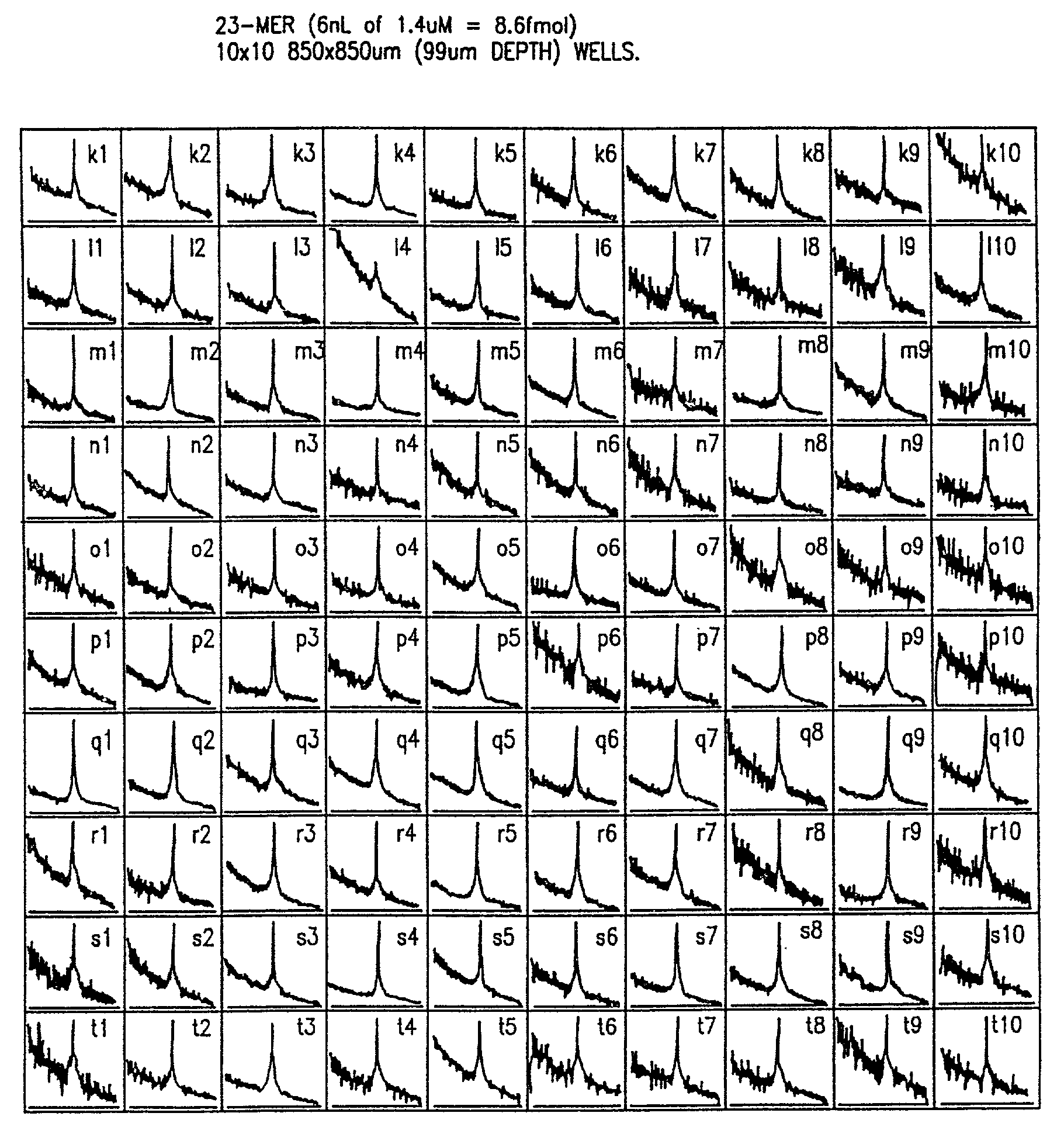
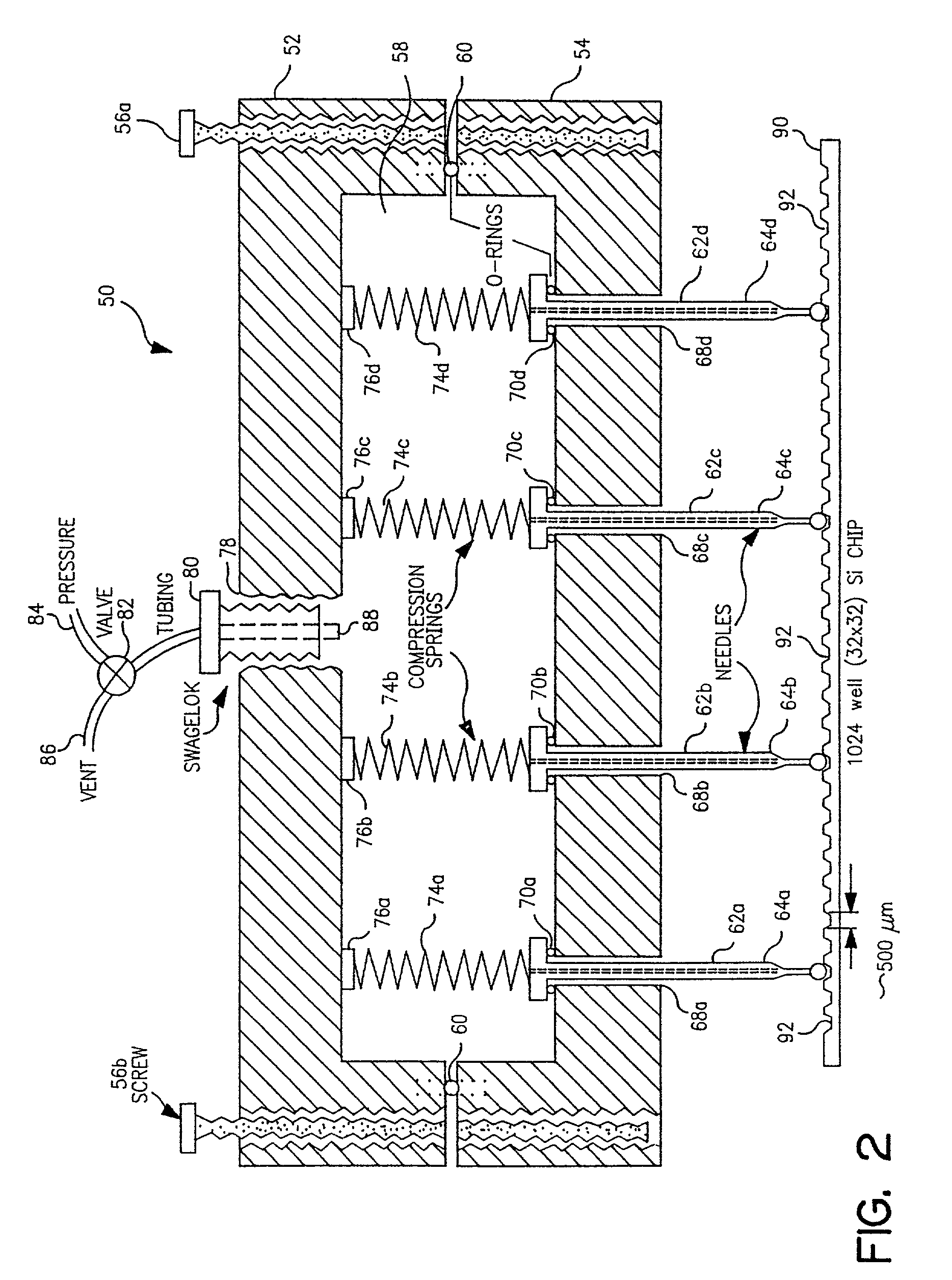
[0076]Robot-driven serial and parallel pL-nL dispensing tools were used to generate 10-103 element DNA arrays on 5. In a second approach, probes from a 384 well microtiter plate are dispensed 16 at a time into chip wells or onto flat surfaces using an array of spring loaded pins which transfer ˜20 nL to the chip by surface contact; MS analysis of array elements deposited with the parallel method are comparable in terms of sensitivity and resolution to those made with the serial method.

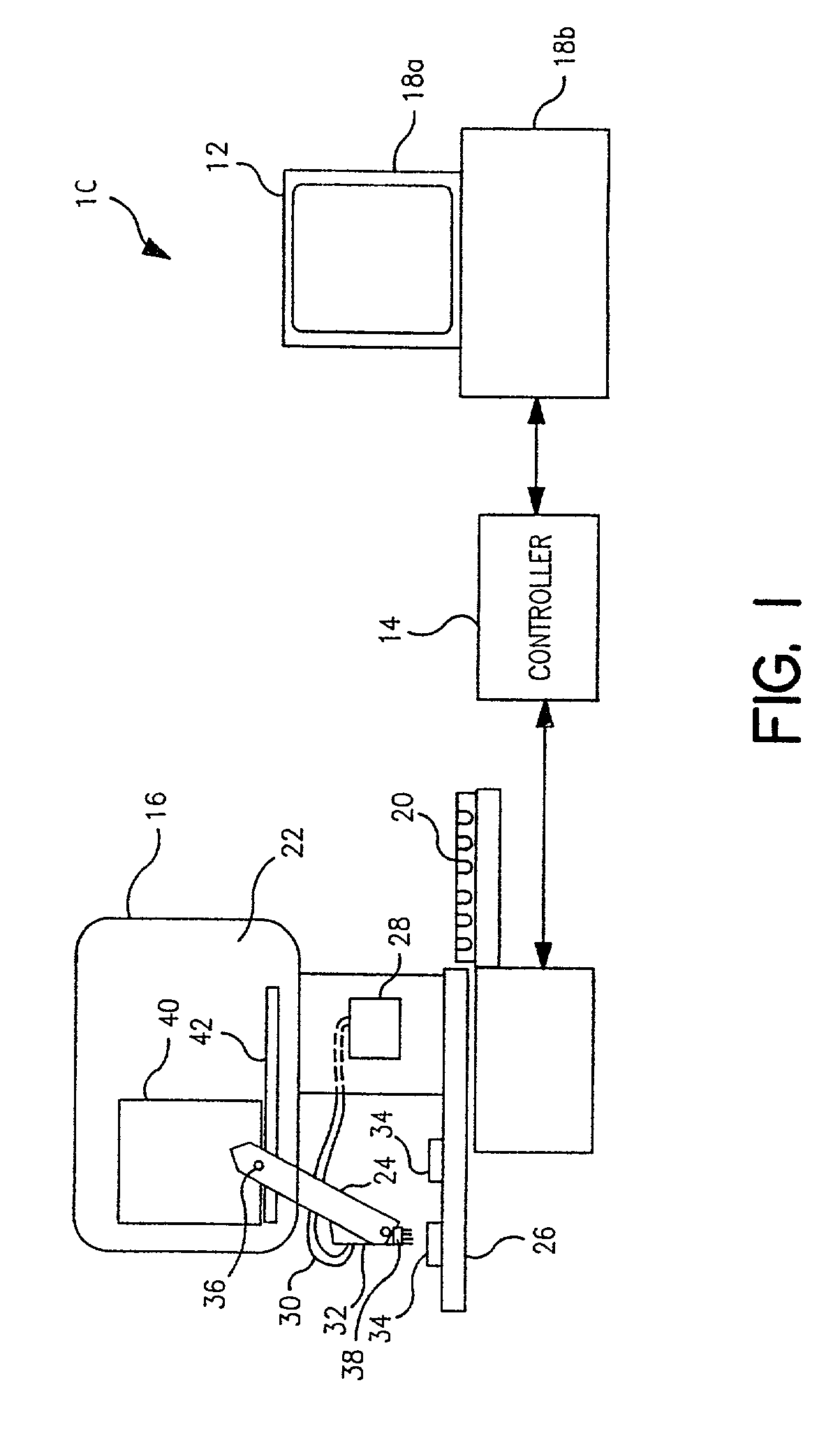
[0077]I. Description of the piezoelectric serial dispenser. The experimental system built on a system purchased from Microdrop GmbH, Norderstedt Germany and consists of a piezoelectric element driver which sends a pulsed signal to a piezoelectric element bonded to and surrounding a glass capillary which holds the solution to be dispensed; a pressure transducer to load (by negative pressure) or empty (by positive pressure) the capillary; a robotic xyz stage and robot driver to maneuver the capillary for...


PUM

PropertyMeasurementUnit
volumeaaaaaaaaaa
sizeaaaaaaaaaa
sizeaaaaaaaaaa

Abstract

The invention provides methods for dispensing tools that can be employed to generate multi-element arrays of sample material on a substrate surface. The substrates surfaces can be flat or geometrically altered to include wells of receiving material. The tool can dispense a spot of fluid to a substrate surface by spraying the fluid from the pin, contacting the substrate surface or forming a drop that touches against the substrate surface. The tool can form an array of sample material by dispensing sample material in a series of steps, while moving the pin to different locations above the substrate surface to form the sample array. The invention then passes the prepared sample arrays to a plate assembly that disposes the sample arrays for analysis by mass spectrometry. To this end, a mass spectrometer is provided that generates a set of spectra signal which can be understood as indicative of the composition of the sample material under analysis.

Description

FIELD OF THE INVENTION[0001]The invention relates to systems and methods for preparing a sample for analysis, and more specifically to systems and methods for dispensing low volumes of fluid material onto a substrate surface for generating an array of samples for diagnostic analysis.BACKGROUND OF THE INVENTION[0002]In recent years, developments in the field of the life sciences have proceeded at a breathtaking rate. Universities, hospitals and newly formed companies have made groundbreaking scientific discoveries and advances that promise to reshape the fields of medicine, agriculture, and environmental science. However, the success of these efforts depends, in part, on the development of sophisticated laboratory tools that will automate and expedite the testing and analysis of biological samples. Only upon the development of such tools can the benefits of these recent scientific discoveries be achieved fully.[0003]At the forefront of these efforts to develop better analytical tools...

Claims


Application Information

Patent Timeline
Patent Type & Authority Patents(United States)
IPC IPC(8): G01N1/10B01J19/00B01L3/02C07B61/00C07F9/24C07H21/00C12Q1/68C40B40/06C40B40/10C40B60/14G01N35/10
CPCB01J19/0046B01L3/0262B01L3/0268C07F9/2408C07F9/2429C07H21/00G01N35/1067B01L3/0244H01J49/0418Y10T436/25B01J2219/00317B01J2219/00387B01J2219/00468B01J2219/00497B01J2219/005B01J2219/00504B01J2219/00511B01J2219/0052B01J2219/00527B01J2219/00585B01J2219/00596B01J2219/00605B01J2219/0061B01J2219/00612B01J2219/00621B01J2219/00637B01J2219/00641B01J2219/00648B01J2219/00659B01J2219/0072B01J2219/00722B01J2219/00725C07B2200/11C40B40/06C40B40/10C40B60/14G01N35/1074G01N2035/1037G01N2035/1069B01J2219/00378Y10T436/24Y10T436/2575Y10T436/119163Y10T428/26B01J2219/00315Y10T428/31855Y10T428/31678
Inventor LITTLE, DANIEL P.O'DONNELL-MALONEY, MARYANNE J.CANTOR, CHARLES R.KOSTER, HUBERT
Owner AGENA BIOSCI
Learn More