Collision cell for mass spectrometer

a mass spectrometer and collision cell technology, applied in the field of mass spectrometry, can solve the problems and achieve the effect of reducing the sensitivity and other detriments of mass analysis

Active Publication Date: 2011-04-12
DH TECH DEVMENT PTE
View PDF8 Cites 141 Cited by
  • Summary
  • Abstract
  • Description
  • Claims
  • Application Information

AI Technical Summary

Problems solved by technology

Those skilled in the relevant arts will appreciate that the loss of ions can result in reduced sensitivity and other detriments in mass analysis.

Method used


Image

  • Collision cell for mass spectrometer
  • Collision cell for mass spectrometer
  • Collision cell for mass spectrometer

Examples


Embodiment Construction

[0025]It should be understood that the phrase “a” or “an” used in conjunction with the present teachings with reference to various elements encompasses “one or more” or “at least one” unless the context clearly indicates otherwise.

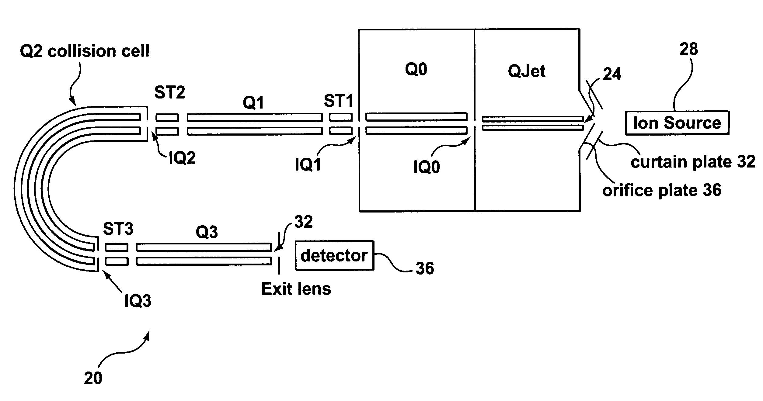
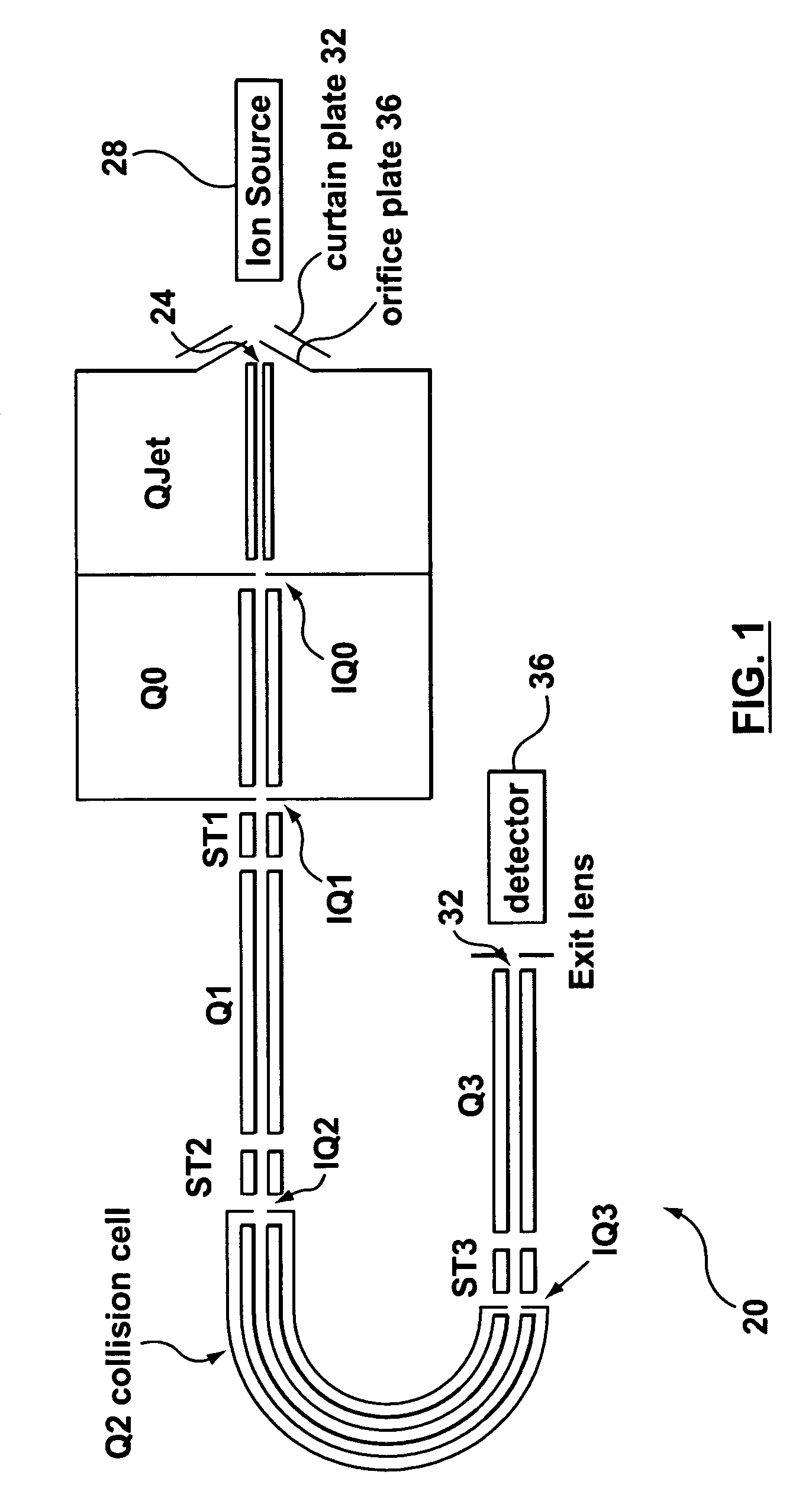
[0026]With reference to FIG. 1, a mass spectrometer (“MS”) in accordance with applicants' teachings is indicated generally at 20. In the illustrated embodiment, MS 20 comprises a quadrupole region QJet (a trademark of Applied Biosystems / MDS Sciex) that includes an opening 24 operable to receive from an ion source 28 sample precursor ions. In the illustrated embodiment, opening 24 is characterized by a curtain plate 32 and an orifice plate 36. In a present embodiment, region QJet operates at a pressure of about two to about four Torr.

[0027]In the embodiment shown in FIG. 1, MS 20 also comprises a collision focusing ion guide region Q0 adjacent to region QJet which receives precursor ions from region QJet via an aperture IQ0, and which expels those ions via ...


PUM


Abstract

A novel curved collision cell for a mass spectrometer is described. The collision cell includes a straight section having a length that is selected to cause a precursor ion entering the straight section to lose a desired amount of kinetic energy such that when the precursor ion enters the curved section of the collision cell the precursor ion will tend to neither escape nor contact the collision cell, and thereby tending to survive its passage within the curved portion.

Description

[0001]The present application claims the benefit of U.S. Provisional Patent Application No. 60 / 973,547, filed Sep. 19, 2007, the contents of which are incorporated herein by reference.[0002]The section headings used herein are intended as organizational aids, and are not to be construed as limiting the subject matter of the teachings in any way.FIELD[0003]Teachings herein relate generally to mass spectrometry, and to novel collisions cells for mass spectrometers.INTRODUCTION[0004]In mass spectrometry, two mass analyzers can be used in series separated by a collision cell. In a collision cell, precursor ions are fragmented by collision-induced dissociation, to produce a number of product ions. Alternatively, the precursor ions may undergo reactions in the collision gas to form adducts or other reaction products. The term “product ion” is intended to mean any of the ion products of the collisions between the precursor ions and the gas molecules in the collision cell. The product ions ...

Claims


Application Information

Patent Timeline
Patent Type & Authority Patents(United States)
IPC IPC(8): B01D59/44
CPCH01J49/063H01J49/0045
Inventor COLLINGS, BRUCE A.GUNA, MIRCEA
Owner DH TECH DEVMENT PTE
Why Eureka
Try Eureka