Image forming apparatus having an image forming part that can be set in a standby state in response to image forming operation to be performed subsequently
- Summary
- Abstract
- Description
- Claims
- Application Information
AI Technical Summary
Benefits of technology
Problems solved by technology
Method used
Image

Examples
Embodiment Construction
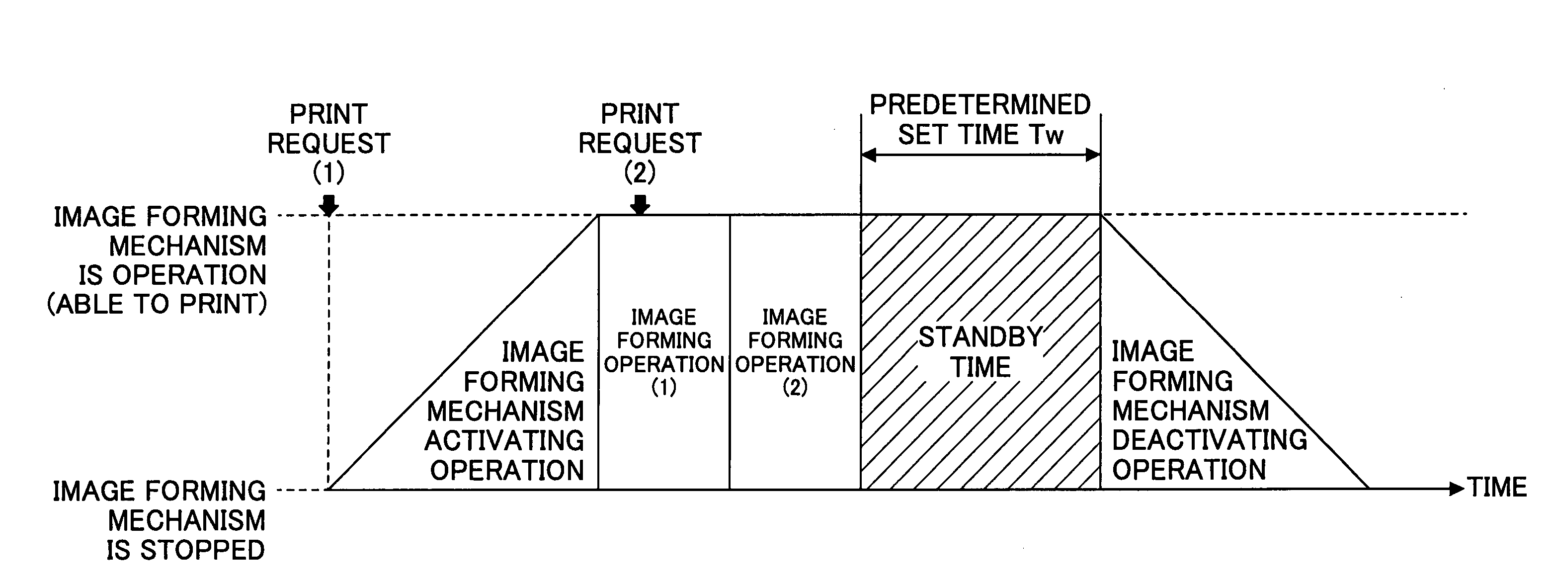
[0032]A description will now be given, with reference to the drawings, of an image forming apparatus according to a first embodiment of the present invention. The image forming apparatus according to the first embodiment of the present invention optimizes a timing of inactivating an image forming part so as to improve throughput of the image forming process by performing an inactivating operation of the image forming part after waiting a passage of a predetermined time without immediately inactivating the image forming part after an image forming operation of one print job is completed by the image forming part.
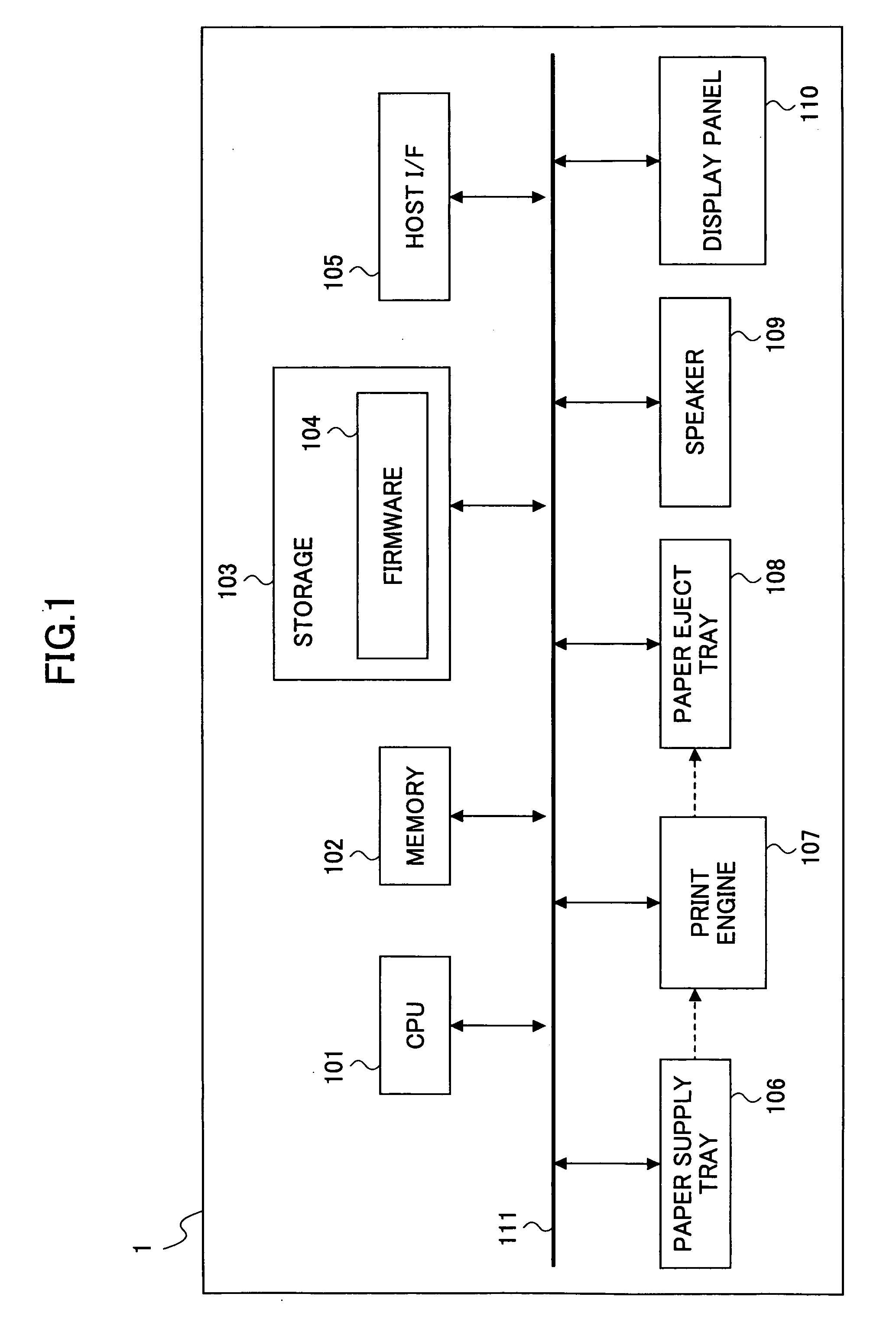
[0033]FIG. 1 is a hardware block diagram of the image forming apparatus 1 according to the first embodiment of the present invention. As shown in FIG. 1, the image forming apparatus 1 comprises a central processing unit (CPU) 101, a memory 102, a storage 103, a host interface (I / F) 105, a paper supply tray 106, a print engine 107, a paper eject tray 108, a speaker 109, a disp...
PUM
 Abstract
Description
Claims
Application Information
 - R&D
- Intellectual Property
- Life Sciences
- Materials
- Tech Scout
- Unparalleled Data Quality
- Higher Quality Content
- 60% Fewer Hallucinations
Browse by: Latest US Patents, China's latest patents, Technical Efficacy Thesaurus, Application Domain, Technology Topic, Popular Technical Reports.
© 2025 PatSnap. All rights reserved.Legal|Privacy policy|Modern Slavery Act Transparency Statement|Sitemap|About US| Contact US: help@patsnap.com