Plastic overmolded screw

a screw and plastic technology, applied in the direction of screws, threaded fasteners, bolts, etc., can solve the problems of reducing the area and the integrity of the plastic cover on the head, and affecting the performance of the screw head, so as to maximize the size of the plastic material, avoid exposing, and save costs

Inactive Publication Date: 2008-07-10
TECHFORM PRODS
View PDF10 Cites 27 Cited by
  • Summary
  • Abstract
  • Description
  • Claims
  • Application Information

AI Technical Summary

Benefits of technology

[0008]The present invention overcomes the above mentioned disadvantages by providing a method and a product produced by the method for plastic molding, over the screw head, for example, by injection molding with a fastener insert. The resulting product avoids exposing the plastic body to abusive or detrimental forces by assuring the force is applied to the fastener, often made of metal, in connection with turning or engaging the screw during fastening. The result may be accomplished without interior, recessed machining of the metal screw body before injection molding to reinforce the plastic material. For example, on a hex head bolt, or similar polygonally or otherwise shaped screw head, the side walls of the screw head intermediate the tool engagement points of the hex head may be notched to receive plastic during an insert molding operation. Preferably, in one embodiment, the areas intermediate the points of the apexes on the head of a fastener may be concavely grooved by machining, forming or grinding. This and other embodiments may leave portions of the contact surfaces of the screw head sidewalls near to the points or apexes exposed for control with the contact surfaces of a driver socket or wrench, without directly contacting or applying force to a portion of the plastic overmolding.
[0009]In a preferred embodiment, substantial portions of the six points of the hex are exposed. The injection molded plastic covers the top and fills notches in the screw head. Since the hex points of this example are exposed, the driver socket only makes contact with the metal head portions, and the screw may be driven no matter how soft or resilient the covering may be. Preferably, while portions of the screw head adjacent the six points may be exposed, other portions s

Problems solved by technology

If the whole head of the screw were soft plastic, a driver would strip or damage the head during installation.
This substantially reduces the area and the integrity of the plastic cover on the head.
Accordingly, repeated impacts with the plastic layer on the head must be absorbed by a smaller mass of plastic material and induces

Method used


Image

  • Plastic overmolded screw
  • Plastic overmolded screw

Examples


Embodiment Construction

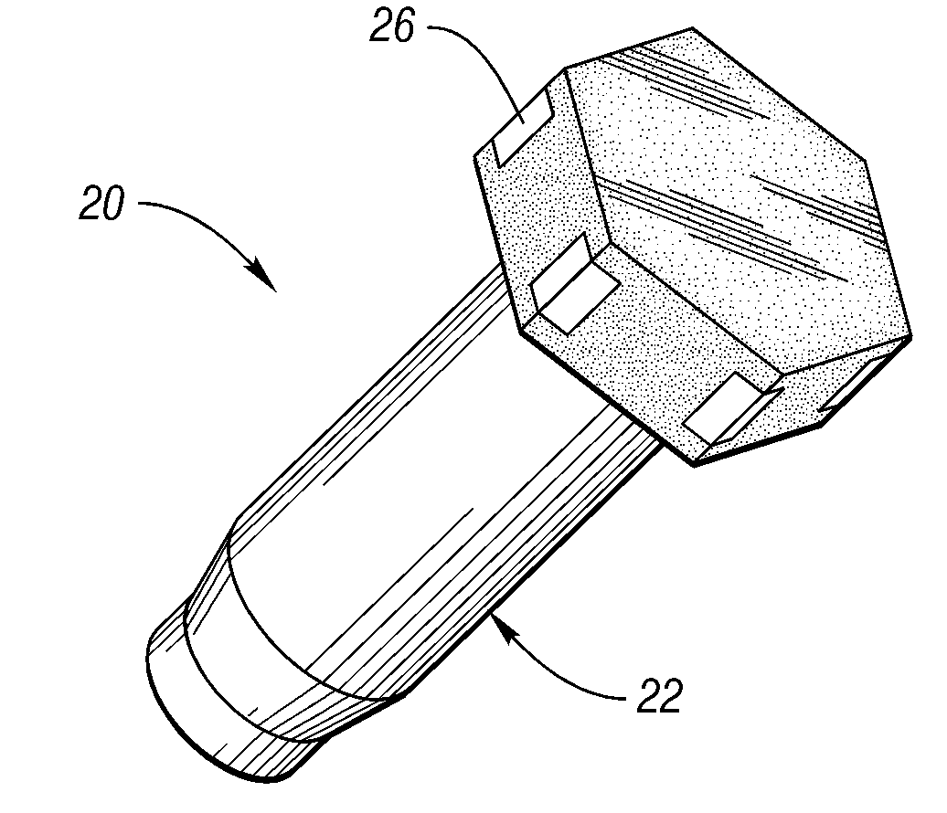
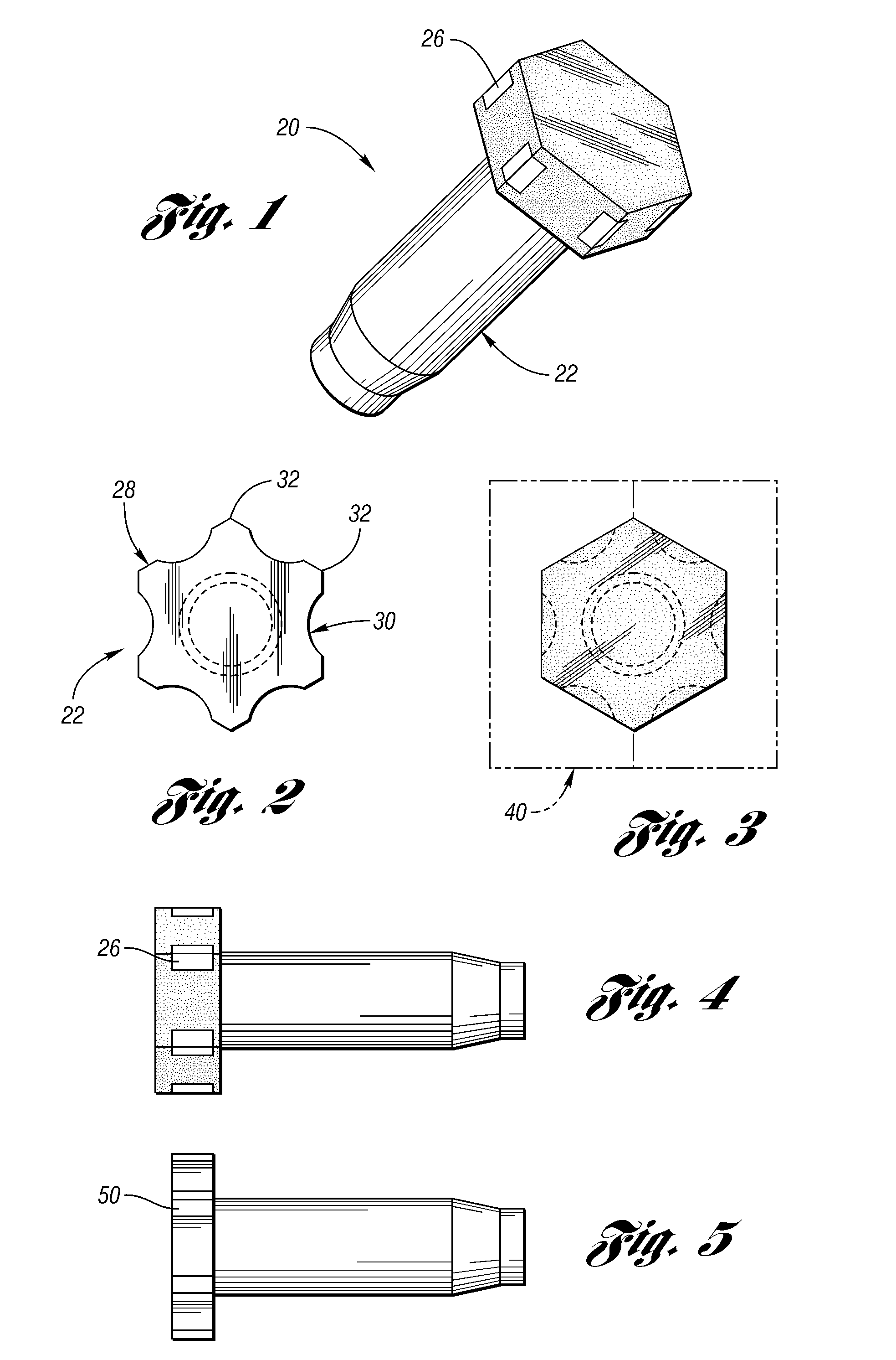
[0018]Referring first to FIG. 1, a product 20 is there shown comprising a fastener part 22 carries an overmolded layer 24. The fastener part 22 may be formed in the manner of many previously known fasteners adapted to be engaged by tools for installing a fastener in a part. For example, screws with hex heads are very commonly available and may be used as the fastener inserts. Nevertheless, it is to be understood that material employed in forming the fastener part 22 is not limited to metal. Similarly, the overmolded portion 24 may be a substantially softer material as may be desirable to provide a cushioning surface and intended to perform as a bumper screw. Nonetheless, it is to be understood that the overmolded material is not limited to any particular performance characteristics or bumper applications, depending only upon the end use to the product as made. As a result, it will be understood to those of ordinary skill in the art that the overmolded portion 24 and the fastener 22 ...


PUM

PropertyMeasurementUnit
Resilienceaaaaaaaaaa
Exposure limitaaaaaaaaaa

Abstract

A two-piece fastener, for example a bumper screw, includes a fastener and an overmolded resilient portion configured to avoid contact with a fastening tool.

Description

CROSS-REFERENCE TO RELATED APPLICATIONS[0001]This application claims the benefit of U.S. provisional application Ser. No. 60 / 879,695, filed Jan. 10, 2007, the disclosure of which is hereby incorporated in its entirety.BACKGROUND OF THE INVENTION[0002]1. Field of the Invention[0003]The invention relates to overmolded fasteners that act as hard stops in automotive body structures.[0004]2. Background Art[0005]Screws are often used in mechanisms to create an adjustable hard stop between one part of a mechanism and another. When the one part of the mechanism hits the screw, a contact sound is made. In a vehicle, these contact noises need to be eliminated. For example, a vehicle closure hinge mechanism may permit the closure's position with respect to an adjacent body panel to be aligned at a height for proper fit and finish. Some previously known bumper screws have tried to put plastic on the top of the screw head. The plastic should be attached to the screw head so that it will not fall...

Claims


Application Information

Patent Timeline
IPC IPC(8): F16B23/00F16B37/14F16B33/00B29C45/14
CPCB29C45/14311B29C45/14336F16B37/14B29K2705/00F16B35/06B29C45/14778
Inventor REYNOLDS, MATTHEW JOHNMCINTYRE, ANDREW REGINALD
Owner TECHFORM PRODS
Why Eureka
Try Eureka