
Image forming method and apparatus

Inactive Publication Date: 2008-07-10
FUJIFILM CORP
View PDF5 Cites 123 Cited by
  • Summary
  • Abstract
  • Description
  • Claims
  • Application Information

AI Technical Summary

Benefits of technology

[0010]The present invention has been contrived in view of the foregoing circumstances described above, an object thereof being to provide an image forming method and image forming apparatus of an intermediate transfer type, whereby ink on an intermediate transfer body can be transferred satisfactorily to a recording medium, while achieving good adhesion of the ink to the recording medium and good strength of the ink film as well as preventing the residual monomer in the ink (i.e., the ink film on the recording medium) from migrating out.

Problems solved by technology

However, in the cases of recording media having high permeability (permeable media), such as normal paper, the ink liquid permeates into the recording medium, and image deterioration occurs due to ink bleeding or dot spreading (dot shape abnormality), or the like.
However, in the case of the ink which is only raised in viscosity and which remains in a liquid state even after the semi-curing on the intermediate transfer body, as described in Japanese Patent Application Publication No. 10-250052, when transferring the ink to the recording medium, not all of the ink is transferred to the recording medium and a portion of the ink is liable to remain on the intermediate transfer body.
However, in the case of an ink having a high monofunctional monomer ratio, the ink having been transferred to the recording medium has a low polymer cross-linking ratio, and consequently the film (i.e., ink film) of the ink on the recording medium has unsatisfactory strength and solvent resistance.
Moreover, the ratio of the low molecular weight component (the component having a low degree of polymerization) in the cured ink is high, and residual monomer which has not been polymerized, or low-molecular weight component which has a low degree of polymerization, is liable to migrate out from the ink film after fixed on the recording medium.

Method used


Image

  • Image forming method and apparatus
  • Image forming method and apparatus
  • Image forming method and apparatus

Examples


first embodiment

Composition of Image Forming Apparatus

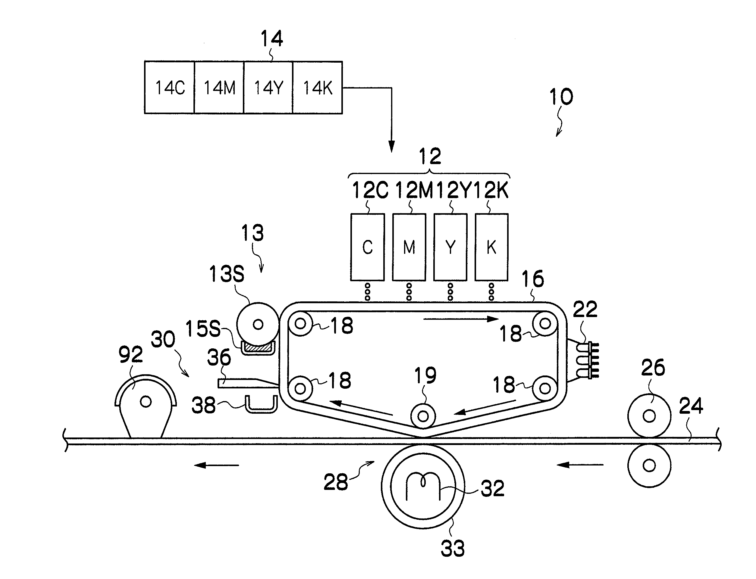
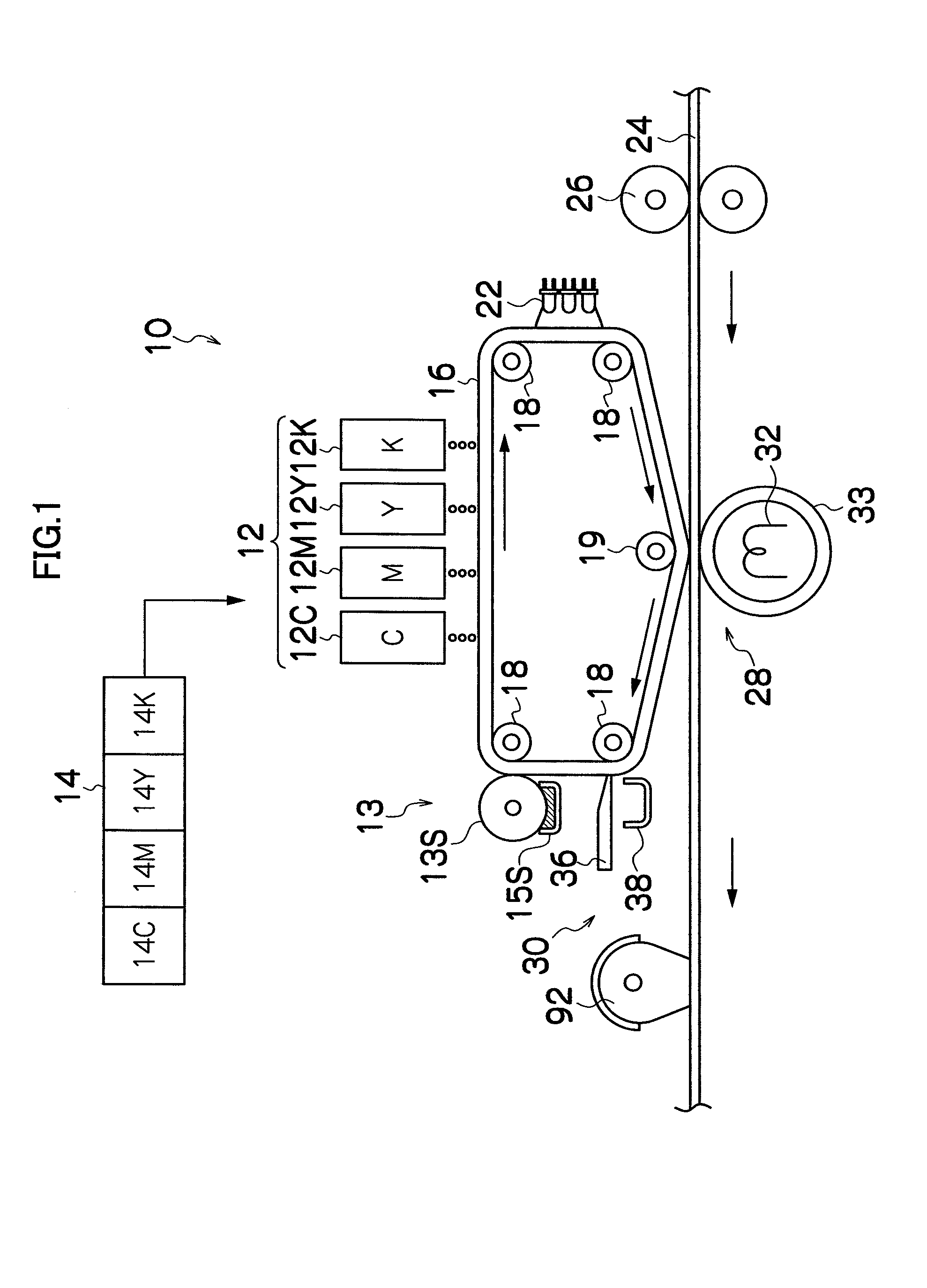
[0040]FIG. 1 is a schematic drawing of an inkjet recording apparatus as an image forming apparatus according to a first embodiment of the present invention. As shown in FIG. 1, the inkjet recording apparatus 10 includes: a print unit 12 having a plurality of inkjet heads (hereinafter called “heads”) 12C, 12M, 12Y and 12K corresponding to inks of respective colors of cyan (C), magenta (M), yellow (Y) and black (K); an ink storing and loading unit 14, which stores inks to be supplied to the respective heads 12C, 12M, 12Y and 12K; and an intermediate transfer body 16, on which an image (primary image) is formed by means of inks ejected as droplets from the heads 12C, 12M, 12Y and 12K.

[0041]The inks used in the present embodiment are radiation-curable inks, each of which contains a radiation polymerizable compound and a coloring material (e.g., pigment) of the corresponding color. The details of the ink composition are described hereinafter.

[0042]Th...

second embodiment

[0189]Next, a second embodiment of the present invention is described. FIG. 7 is a general schematic drawing of an inkjet recording apparatus 300 according to the second embodiment of the present invention. Items which are the same as or similar to those in the first embodiment described above are labeled with the same or similar reference numerals and description thereof is omitted here.

[0190]As shown in FIG. 7, an intermediate transfer body 302 has a round cylindrical shape. In a mode where a drum-shaped member of this kind is used for the intermediate transfer body 302, a beneficial effect is obtained in that the throw distance (namely, the distance between the nozzle forming surfaces of the heads 12C, 12M, 12Y and 12K, and the intermediate transfer body 16) is stable. In a mode, on the other hand, where an intermediate transfer body 16 formed by a belt-shaped member as shown in FIG. 1 is used, it is possible to dispose the heads of a plurality of colors 12C, 12M, 12Y and 12K in ...

third embodiment

[0194]Next, a third embodiment of the present invention is described. FIG. 8 is a general schematic drawing of an inkjet recording apparatus 400 according to a third embodiment. In FIG. 8, items which are the same as or similar to those of the composition shown in FIGS. 1 and 7 are denoted with the same reference numerals and description thereof is omitted here.

[0195]The inkjet recording apparatus 400 shown in FIG. 8 is an intermediate transfer type of apparatus that uses an electron beam curable ink containing a polymerizable compound that is cured by polymerization when irradiated with an electron beam, and the inkjet recording apparatus 400 includes an electron beam irradiation device as the second radiation source 92, which fixes the ink on the recording medium 24 by curing the ink by polymerization.

[0196]The electron beam irradiation device has a structure in which an electron beam generating source 414 is disposed inside a chamber (irradiation chamber) 412 into which nitrogen ...


PUM

PropertyMeasurementUnit
Temperatureaaaaaaaaaa
Fractionaaaaaaaaaa
Fractionaaaaaaaaaa

Abstract

The image forming method includes the steps of: ejecting and depositing an ink containing a coloring material and a radiation polymerizable compound on an intermediate transfer body, the radiation polymerizable compound having a molecular structure including a radical polymerizable group and a cationically polymerizable group; then irradiating the ink on the intermediate transfer body with a first radiation so that one of the radical polymerizable group and the cationically polymerizable group is selectively polymerized and cured; then heating the selectively polymerized and cured ink to a temperature not lower than a softening point of the selectively polymerized and cured ink and not higher than a temperature above the softening point by 10° C., while transferring the selectively polymerized and cured ink from the intermediate transfer body to a recording medium; and then irradiating the ink on the recording medium with a second radiation so that the other of the radical polymerizable group and the cationically polymerizable group is polymerized and cured.

Description

BACKGROUND OF THE INVENTION[0001]1. Field of the Invention[0002]The present invention relates to an image forming method and apparatus, and more particularly, to an intermediate transfer type of image forming method and apparatus, in which an image is formed on a recording medium by transferring an image (ink image) formed on an intermediate transfer body to the recording medium.[0003]2. Description of the Related Art[0004]There has been known an image forming method based on a so-called intermediate transfer system, in which an image is formed on an intermediate transfer body, and the image formed on the intermediate transfer body is then transferred to a recording medium.[0005]There has also been known an image forming method based on a so-called direct recording system, in which a desired image is formed by ejecting droplets of radiation-curable ink directly onto a recording medium. This method is suitable for recording onto a recording medium (low permeability media or non-perme...

Claims


Application Information

Patent Timeline
IPC IPC(8): C08F2/46B05B17/00B41J2/01B41M5/00C09D11/00C09D11/30
CPCB41J2/0057B41J11/002C08F2/48B41J2202/20B41J2002/14459B41J11/00212B41J11/00214
Inventor MAENO, YUTAKAKADOMATSU, TETSUZO
Owner FUJIFILM CORP
Learn More