Tool for making drill-holes in bones or removing cylindrical drill-hole cores from bones of the human body

a technology for bones and tools, applied in the direction of turning apparatuses, medical science, sleeve/socket joints, etc., can solve the problem of no longer being fixed axially in the tool holder, and achieve the effect of facilitating the pushing-on of u-shaped cuts and reducing cross-sectional area

Active Publication Date: 2008-07-10
REINHARD FEINMECHANIK
View PDF4 Cites 10 Cited by
  • Summary
  • Abstract
  • Description
  • Claims
  • Application Information

AI Technical Summary

Benefits of technology

[0007]Advantageously, in a continuation of the concept of the invention, the arrangement is such that the tongue has a reduced cross-sectional area in the region of its tongue root due to the provision of a hole through the tongue wall. Depending on the size and geometric shape of this opening, just two narrow webs from the wall of the already thin-walled tubular tool body remain on either side of the hole as far as the tongue edge, so that the tongue, prior to removal of the tool from the tool holder, can easily be bent out of the opening in the tool holder from outside and moved permanently into the interior of the tubular tool body. Any residual elasticity of the tongue still remaining at the start of the bending-out process is quickly converted into a plastic deformation, i.e. permanent deformation, so that the tool thus made unusable can be pulled out of its tool holder and discarded. Given a suitable choice of material for the tool body, which is preferably made of a corrosion-resistant austenitic or martensitic steel, and given a suitable size and shape of the hole in the tongue root and a sufficiently large bending-out travel, the tongue may even break in the region of the two thin webs during the bending-out process, which is especially desirable in the context of the tool then being unusable.
[0008]Advantageously, the protrusion protruding from the inner wall surface of the tool holder is part of a round bolt fixed radially in a bore of the tool holder, while the cutout in the tool body which receives the protrusion is U-shaped with two wall surfaces parallel to one another and to the longitudinal axis of the tool body. The round bolt can be inseparably connected to the tool holder by welding or soldering. Its round cross-sectional shape facilitates the pushing-on of the U-shaped cutout of the tool body when inserting the tool body into the tool holder.

Problems solved by technology

With the tool thus made unusable, the tool body can be pulled out of the tool holder and reinserted, but it can no longer be fixed axially in the tool holder due to the fact that the tongue has become unusable.

Method used


Image

  • Tool for making drill-holes in bones or removing cylindrical drill-hole cores from bones of the human body
  • Tool for making drill-holes in bones or removing cylindrical drill-hole cores from bones of the human body
  • Tool for making drill-holes in bones or removing cylindrical drill-hole cores from bones of the human body

Examples


Embodiment Construction

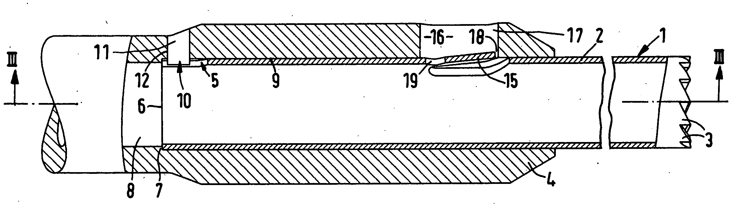
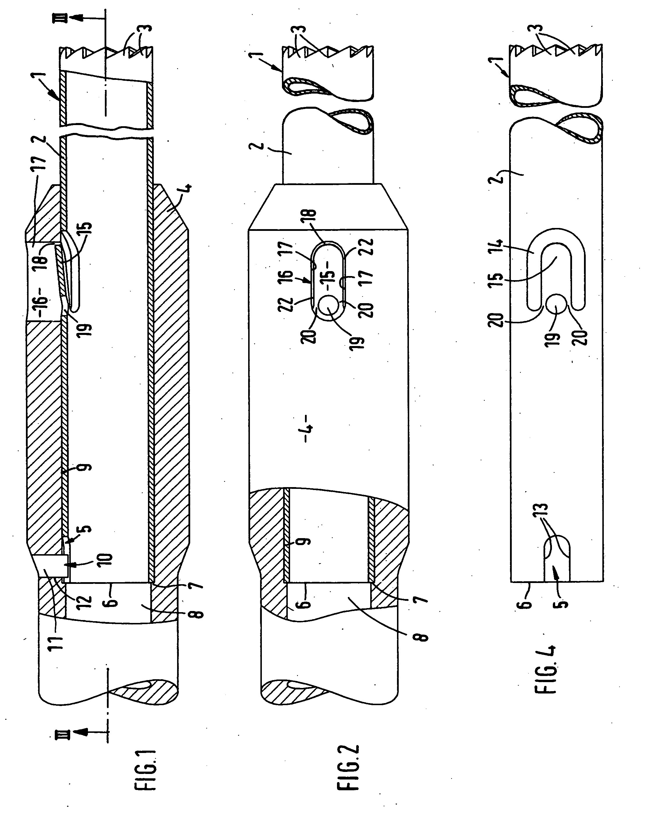
[0021]Reference is firstly made to FIGS. 1 to 4. As can be seen therefrom, the tool generally denoted by reference numeral 1 consists of a thin-walled tubular tool body 2 made of steel, which is provided with cutting or grinding elements 3 at its outer end. In the example shown, these are teeth-like cutting elements. The tool body 2 is inserted axially into a likewise tubular tool holder 4, which tightly surrounds the tool body 2 but allows displacement movements of the tool body 2 during insertion into the tool holder and removal from the tool holder. The tool holder 4, which is shown broken off at its inner end, can be connected to a drive device (not shown) for driving the tool holder 4 and thus the tool 1 in rotation.

[0022]Provided at the inner end of the tool body 2 is a cutout 5 which passes through the wall thickness of the tool body 2 and extends as far as the end face 6 of the tool body 2, i.e. is open towards this side. When the tool body is fully inserted, this end face 6...


PUM


Abstract

A tool (1) is constructed for single use for making drill-holes in bones or removing cylindrical drill-hole cores from bones of the human body with a tubular tool body (2) which can be inserted into a receiving bore (8) of a tool holder (4). At least one cutout (5) in the tool body (2) and at least one protrusion (10) of the tool holder are coupled to rotationally affix the tool (1) to the tool holder (4). In the process, a flexible tongue (15) on the tool body (2) latches into an opening (16) of the tool holder (4) to axially fix the tool body. After the tool (1) has been used, the tongue (15) can be pushed out of the opening from outside, with plastic deformation, so that the tool can no longer be connected to the tool holder (4).

Description

TECHNICAL FIELD[0001]The invention relates to a tool for making drill-holes in bones or removing cylindrical drill-hole cores from bones of the human body, according to the preamble of claim 1.PRIOR ART[0002]In reconstructive surgery, tools which are driven in rotation and which have a cutting and / or grinding action are used to make drill-holes in bones and to obtain cylindrical drill-hole cores from bones. For the operator, it is not always possible in an unambiguous manner to assess the cutting or grinding elements of the tools with regard to a sufficient cutting or grinding performance. Therefore, in order to achieve a sufficient cutting or grinding performance, the tools should be used just once. However, the known tool designs can be connected to and detached from the tool holder of the drive device as often as desired, so that one-off use is not guaranteed.PROBLEM[0003]The problem on which the invention is based is that of providing a tool which is designed as a tool for singl...

Claims


Application Information

Patent Timeline
Patent Type & Authority Applications(United States)
IPC IPC(8): A61B17/00
CPCA61B17/162A61B17/1637Y10T279/17162B23B51/0473A61B2017/00969
Inventor REINHARD, HELMUT
Owner REINHARD FEINMECHANIK
Why Eureka
Try Eureka